
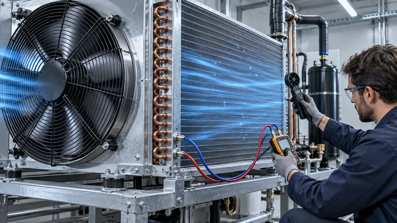
The AC fan passed the room test and failed outdoors
Outdoor HVACR and electrical equipment can turn a clean, stable fan test into a high-ambient, dusty and condensation-prone duty cycle.
A condenser, heat-exchanger cabinet or outdoor electrical enclosure may pass a factory thermal test and still lose cooling margin after installation. The site may have stronger solar gain, a hotter inlet, a smaller effective louvre area, dust that loads the filter, or a restart after rain when surfaces are wet. The fan is often blamed because it is visible, but the real failure is usually a mismatch between the tested air path and the installed environment.
AC axial fans remain practical for fixed-speed ventilation when 110 V or 220 V AC is already available. Their selection is not complete when the frame fits and the motor spins. The product must start at the actual terminal voltage, move useful air through the production restriction, survive the defined ambient and humidity conditions, and remain serviceable when dust and water exposure change the system resistance.
This guide gives a field-oriented sequence for HVACR outdoor units, condenser sections, inverter cabinets, generator controls and industrial power enclosures. It keeps the commercial boundary precise: MEGA Tech develops and manufactures custom cooling fans; the complete HVACR unit, coil, controller, cabinet sealing and system integration remain with the equipment manufacturer or system integrator.
The important distinction is between a component qualification and an installation qualification. A fan may be electrically healthy and still be unsuitable for the pressure, temperature or moisture path created by the final equipment. The field test should therefore preserve the actual cutout, guard, filter, louvre, cable route and service access. That evidence helps the engineering team decide whether to change the fan, enlarge the filter, control recirculation or revise the enclosure before the problem becomes a production return.

Define the outdoor duty before choosing a fan
Ambient temperature is only one line in the requirement; the fan sees a combined thermal, electrical, mechanical and air-side duty.
Write the worst operating modes first. Include the highest expected inlet air temperature, solar-exposed surfaces, simultaneous compressor or inverter load, dirty-filter condition, low-load cycling, night-time restart and any defrost or purge sequence. If the equipment is installed near a wall or another unit, note the recirculation risk and the clearance that was actually tested.
Separate the air temperature entering the fan from the temperature around the motor and bearing. A fan mounted in an exhaust path can see air that has already crossed a heat exchanger or power module. A fan mounted near a sunlit panel can see a local temperature that is higher than the weather-station value. Record the measurement location and the duration of the hot condition.
The electrical duty also belongs in the same record. State 50 Hz or 60 Hz, nominal voltage, measured terminal voltage, startup sequence, switching device, operating hours and the number of starts. A fan that runs continuously has a different review from one that cycles with a thermostat or compressor.
If the unit is installed in a row of equipment, capture the spacing and neighboring exhaust directions. Warm air from one unit can become the inlet condition for the next. Record whether the test uses a roof, wall or skid-mounted arrangement, because the same fan and same heat load can have different margin when the discharge recirculates. Include the wind or shelter condition when it materially changes the outlet plume, and identify the farthest or hottest unit in a multi-unit installation.
| Duty input | Record for the design review | Selection consequence |
|---|---|---|
| Heat and ambient | Heat load, inlet temperature, solar exposure, local recirculation | Sets airflow target, temperature margin and sample condition |
| Air path | Louvre, filter, guard, coil, grille, service condition | Sets system resistance and useful operating point |
| Moisture | Humidity, rain, dew point, drainage and restart state | Defines condensation and maintenance checks |
| Electrical | Voltage, frequency, terminal drop, switching and cycles | Determines valid AC data and startup evidence |
| Service | Dust load, cleaning interval, access and replacement method | Changes pressure, reliability and life assumptions |
Use heat load and temperature rise to set airflow
Do not select from the free-air CFM value before defining the allowable temperature rise at the protected component.
List the losses that operate together: compressor-side electronics, inverter switches, rectifiers, contactors, transformers, power supplies, control boards and any heat from the surrounding machine. Use the equipment designer's loss data where available. The electrical input rating is not automatically the heat load because energy can leave through the load, refrigerant circuit or other paths.
For an initial air-side screen, use the sensible-heat relationship Q = P/(rho x cp x Delta T), with heat P in watts, air density rho, specific heat cp and permitted temperature rise Delta T. This is a screening estimate. Altitude changes density, hot outdoor air reduces mass flow for the same volume flow, and nonuniform component heating can create a local limit that the average cabinet temperature hides.
Define both the average air limit and the tightest local limit. A power semiconductor, capacitor, motor terminal or control board may be the first component to exceed its allowable temperature. Map the intended air path so the selected fan actually reaches that component. If air bypasses the heat source, a higher CFM label will not correct the layout.
Filter loading moves the operating point over time
A clean-filter test is a starting point, not a service-condition approval.
Outdoor equipment often depends on a filter, mesh, louvre or guard to control dust and debris. Each item consumes static pressure. As dust accumulates, the system curve rises and the fan operating point moves to lower airflow. A fan can continue to sound normal while the protected component temperature climbs because the pressure margin was never documented.
Measure or estimate the pressure loss at the target airflow for a clean condition and for the defined service condition. Fit the production filter and frame, not a loose laboratory screen. Check that the gasket seals around the filter; a bypass leak may increase measured total airflow while sending less air through the intended heat source.
Set a maintenance trigger from evidence: differential pressure, temperature rise, airflow, alarm state or a defined service interval. The exact threshold belongs to the equipment design and verified filter data. Do not claim that a fan has solved filter maintenance unless the complete enclosure and service procedure have been tested.
Service access is part of the pressure design. A filter that cannot be removed without disturbing the fan cable may be left in place beyond its intended condition. A replacement filter with a different depth or frame seal can also change the pressure curve. Freeze the service part number, access direction and reassembly method with the cooling specification, then repeat the airflow check after maintenance.
Condensation risk starts with the dew point
Humidity becomes a cooling-fan problem when a cold surface falls below the surrounding air dew point.
A fan does not remove condensation risk by itself. Outdoor equipment can cool a metal panel, coil frame, cable gland or heat sink below the dew point after rain, a night-time temperature drop or a shutdown followed by a warm humid restart. If the fan then starts, it may spread humid air across sensitive surfaces without solving drainage or sealing.
Define the moisture states that the equipment can see: storage, transport, rain exposure, shutdown, restart, defrost and normal running. Note which surfaces can become cold and where water can drain. Keep fan airflow, louvre geometry and drainage features in the same review so the air path does not carry water toward electronics.
Validate the sequence rather than one humidity snapshot. Record inlet temperature, surface temperature, relative humidity or dew-point basis, fan command and the time from shutdown to restart. Inspect for droplets, wet filters, trapped water and corrosion-prone interfaces. MEGA Tech can review fan-side airflow and sample behavior; the system integrator owns enclosure sealing, drainage and environmental protection.
A useful record distinguishes condensation on the air path from water entering from outside. The corrective action is different: one may require a change in surface temperature or restart control, while the other may require a louvre, gasket, drain or enclosure revision. Do not use a fan speed change as a substitute for identifying the water path.
High ambient changes noise, speed and thermal margin
A fixed-speed AC fan may deliver the required volume flow while the hot installation changes component temperature, noise and electrical margin.
Air density falls as temperature rises. If the design requirement is a mass-flow or heat-rejection requirement, the same volume-flow number at hot air does not provide the same cooling capacity as it does in a cool room. Use the correct design basis and verify the protected temperature at the hot condition.
Noise also changes with operating point, turbulence and installation. A filter with a small free area can create higher face velocity and tonal noise. A sun-warmed panel can change mounting stiffness. A fan that is acceptable on a bench can become louder when the guard, louvre and cabinet form a resonant assembly.
Measure sound only after the equipment reaches the defined thermal state and with the production air path installed. Record the measurement distance and background condition. If the result is too loud, review filter area, guard geometry, fan quantity, operating point and mounting before simply reducing speed and losing thermal margin.
High ambient can also expose a false acoustic comparison. Background sound at an outdoor site may mask a tonal component, while a quiet indoor room can make the same component appear unacceptable. Use the same measurement method for candidate samples and note wind, compressor state and nearby equipment. The engineering decision should still be tied to the protected temperature and installed operating point, not to sound alone.
Voltage, frequency and outdoor switching must stay controlled
Outdoor temperature and long cable routes can expose a marginal AC power path that was invisible in the factory test.
Match the catalogue record to the actual 50 Hz or 60 Hz frequency and to the voltage at the fan terminals. Measure during startup and steady operation when the compressor, heater, inverter or other shared load is switching. A source reading at the panel does not prove the value at a remote fan after cable, connector and contact loss.
Record the controller or contactor behavior. Thermostats, pressure switches and PLC outputs may create repeated cycles, delayed starts or simultaneous fan energization. Test brownout recovery and rapid power interruption if those events are possible in the field. The pass condition should include startup completion, stable airflow or pressure and protected-component temperature.
For several fans, test one-fan and all-fan startup. Shared voltage sag, reverse flow through an idle fan and a failed position can change the system result. Staggered starting may reduce electrical stress, but the air path must still protect the heat source throughout the sequence. Include the longest cable route and the actual contactor or thermostat in the test, because a laboratory lead can hide the loss that occurs in the installed branch.
Keep the AC selection record explicit about what is and is not controlled by the fan. Voltage, frequency, airflow, pressure, temperature and noise are fan-side validation inputs. Breaker sizing, protective coordination, enclosure ingress protection and emergency behavior belong to the system designer. This separation prevents an application article or a sample recommendation from implying that the fan alone certifies the complete machine.
A field validation plan for outdoor AC fans
Use a repeatable evidence package for the first sample, a replacement and a production change.
Freeze the configuration: fan series and type, voltage, frequency, bearing, mounting, guard, louvre, filter, cable, switching device and drain arrangement. Photograph the assembly and record the measurement instruments. A replacement must be evaluated as a complete installation, not as a square outline.
Run the clean and service-condition tests. Capture source and terminal voltage, frequency, startup current, steady current, input power, airflow or pressure, inlet temperature, protected temperatures and noise. Let the cabinet reach a repeatable thermal state before approving the result.
Repeat the defined environmental sequence: high ambient, cool restart, humid restart, filter condition, controller cycling and simultaneous equipment load. Inspect for water path, rubbing, vibration, abnormal noise and cable movement. If the design fails, change one variable at a time so the corrective action remains traceable.
Release only with a written pass/fail record. Include the operating point, environmental basis, service condition and exact fan configuration. The record should be good enough for a second engineer to reproduce the decision without relying on a catalogue maximum-airflow number. Keep the raw voltage, pressure and temperature traces with the report; a single averaged value cannot show a short startup dip, a filter bypass or a delayed thermal rise.
When a sample fails, change one variable at a time. Increase filter area, correct the louvre, change the fan configuration, adjust the switching sequence or revise the drain only after the baseline is captured. This approach makes the final production change explainable and avoids selecting a larger fan simply because the first air path was not representative.
- Define the hot inlet and protected-component temperature limits.
- Measure the production filter, louvre and guard pressure loss.
- State the dew-point and drainage sequence for shutdown and restart.
- Capture terminal voltage at 50 Hz or 60 Hz during startup and operation.
- Repeat the test after the defined service or filter-loading condition.
- Record airflow or pressure, noise, vibration and temperature together.
How MEGA Tech supports the fan-side decision
A useful recommendation starts with the operating point and ends with a sample on the customer's actual equipment.
MEGA Tech develops and manufactures custom cooling fans for equipment builders. Our scope covers fan selection, air-path review, sample validation and the transition to volume production. For an outdoor AC application, send the envelope, voltage, frequency, target airflow, target static pressure, quantity, noise target, mounting orientation, filter or grille, ambient range, humidity or dew-point basis and switching method.
Selection should follow the installed operating point rather than a part number or outline dimension. If the problem is high ambient, include the hot inlet and protected-component temperatures. If the problem is condensation, include the shutdown and restart sequence, surface temperatures, drainage and enclosure context. If the fan is being replaced, include the original duty point and the reason for the change.
We are the custom cooling-fan manufacturer. The complete HVACR unit, cabinet, coil, liquid circuit, controller and system integration remain with the equipment manufacturer or system integrator. Samples can be requested for review on the customer's actual unit; send size, voltage, airflow, static pressure, quantity, noise and environment to inquiry@cnmegatech.com or WhatsApp +86 135 7056 7086.
Engineer FAQ
Short answers for an outdoor AC fan design review.
Q: Is a high-temperature room test enough? A: No. Include the production air path, hot inlet, solar or recirculation condition, service filter and protected-component temperature.
Q: Does an AC fan prevent condensation? A: No. Review dew point, cold surfaces, drainage, sealing and the shutdown/restart sequence with the fan test.
Q: Can I approve from maximum CFM? A: No. Use the P-Q curve at the actual voltage and frequency, then validate the installed operating point.
Q: Should I use a bigger fan for dust? A: Not automatically. Review filter area, pressure margin, service condition, bypass and the complete air path.
Q: What should I send for a sample recommendation? A: Send size, voltage, frequency, airflow, static pressure, quantity, noise target, environment, filter, mounting and control details.
Questions for your next outdoor AC fan design review
Use these questions to turn an outdoor cooling complaint into a testable requirement for design review, sample approval and production release.
Keep the environmental record beside the electrical and airflow evidence. That makes it possible to distinguish a fan selection issue from a filter, louvre, drainage, wiring or system-integration issue before a larger fan is installed without understanding the cause. A clear record also gives the supplier the information needed to develop a custom sample and compare it on the real equipment before volume production. It protects both the equipment team and the fan supplier from approving a nominal size without an operating point.
- What hot inlet temperature and local recirculation condition define the worst case?
- What heat load and protected-component temperature limit set the airflow target?
- What are the clean and service-condition pressure losses of the filter, louvre and guard?
- Which voltage and frequency apply at the fan terminals during the worst switching event?
- What dew-point, cold-surface, drainage and restart sequence must be tested?
- What changes after dust loading, rain exposure, shutdown or a hot restart?
- Is the exact fan configuration frozen by voltage, frequency, bearing, mounting and air path?
- What must be sent to MEGA Tech: size, voltage, airflow, pressure, quantity, noise and environment?
