
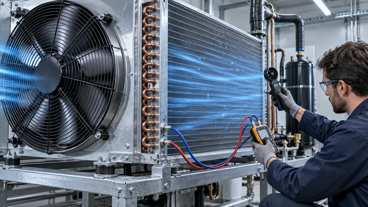
The condenser was sized correctly, but the fan was selected at free air
A heat exchanger only rejects the heat that the installed airflow can carry through its fins. The fan and coil must be selected as one pressure system.
A refrigeration equipment builder replaced a small fan with a larger-looking axial fan after the condenser outlet temperature rose during a hot-day test. On the bench, the replacement showed a higher free-air airflow number. In the equipment, the improvement was smaller than expected because the coil face, protective guard and narrow discharge opening consumed pressure. Part of the airflow also bypassed the useful fin area.
This distinction matters across condensers, evaporators, dry coolers, air-cooled heat exchangers, commercial refrigeration equipment and industrial thermal modules. The fan creates a pressure difference; the heat exchanger converts airflow into heat transfer through its fin field. The installed operating point is the result of both components, not a property of either one in isolation.
This article gives engineers a practical sequence for choosing an AC axial fan for a coil or heat exchanger. It covers heat-load translation, coil pressure drop, 110/220 V and 50/60 Hz selection, air bypass, ambient derating, acoustic checks and sample validation. MEGA Tech's role is custom cooling-fan development and manufacturing, fan selection, air-path review, sample validation and volume production; the complete refrigeration or heat-pump system remains with the equipment builder or system integrator.
Define the heat-rejection duty before choosing frame size
The fan does not cool a nominal coil size. It supports a defined heat-rejection duty at a defined inlet condition.
Write down the heat that must be rejected in the worst operating mode, not just the nominal rating. For a condenser, include compressor input, refrigerant-side operating condition and any heat entering from the cabinet or surrounding equipment. For a dry cooler or air-cooled heat exchanger, identify the fluid temperature, flow rate and required leaving temperature. The fan selection cannot rescue an undersized heat-transfer surface or an unrealistic approach temperature.
Translate the duty into an air-side requirement with the thermal team. A first estimate uses air mass flow, air specific heat and the permitted air temperature rise. That estimate must then be checked against the coil manufacturer's data, because fin spacing, tube arrangement, moisture, frost and face velocity change the effective performance. Keep the air inlet temperature visible: a fan that works at 25°C may not deliver the same thermal margin when the outdoor air is 40°C.
Separate the heat exchanger's thermal requirement from the fan's mechanical rating. The coil may require a minimum face velocity for heat transfer, while the fan may have a maximum allowable noise, current or speed. If several fans are used, define whether the system must continue operating with one fan unavailable, or whether the equipment safely shuts down. That decision changes quantity, spacing, blanking and control requirements.
| Design input | Record | Selection consequence |
|---|---|---|
| Heat duty | Worst-case heat to reject | Sets the required air-side capacity |
| Air inlet | Ambient, recirculated or mixed air temperature | Changes density and thermal margin |
| Coil | Face area, fin spacing and pressure drop | Creates the main system resistance |
| Packaging | Guard, grille, duct and clearances | Adds losses and can cause bypass |
| Duty | Continuous, staged or fault condition | Sets validation time and fan quantity |
Read the coil pressure drop and fan P-Q curve together
The pressure drop across the heat exchanger is not a footnote. It is the load against which the AC fan must produce useful airflow.
Ask for the heat exchanger pressure-drop data at the expected airflow range. If the coil supplier gives only one point, record the limitation and measure the installed assembly during sample testing. Add the losses of the guard, inlet screen, filter, louvre, discharge grille and any transition piece. A short transition can be more restrictive than its drawing suggests when it creates separation or blocks part of the fan circle.
Overlay that system resistance on the AC fan's P-Q curve at the actual voltage and frequency. The intersection gives the estimated operating point. A fan with a high maximum airflow but a shallow pressure curve may be a poor match for a dense coil. Conversely, a high-pressure fan can be wasteful or too noisy if the coil is open and the system needs mostly volume flow.
Do not use a curve from a different frame, type, voltage or frequency just because the dimensions match. The AC catalogue includes 50 Hz and 60 Hz data for many families, and the speed, current, power, airflow, pressure and noise can all change with frequency. Put the curve identifier in the design record so the production sample can be checked against the same reference.

Face velocity, bypass and spacing can defeat a good fan
The airflow that crosses the fin field is the useful flow. Air that goes around the coil contributes little to heat transfer.
Inspect the sealing between the fan panel and the heat exchanger. Gaps around the frame, an oversized cutout or a missing gasket can create a low-resistance bypass. The fan may show a normal current and sound while a portion of its flow avoids the fin field. Use smoke visualization, streamers, pressure mapping or a grid of velocity measurements to find the bypass during the sample review.
Spacing matters when multiple axial fans share a coil. Fan circles should cover the useful face area without creating dead zones between modules. A fan mounted too close to the coil can see a nonuniform inlet and an uneven pressure field. A fan mounted too far away may require a plenum that adds volume but also creates opportunities for recirculation. The correct spacing depends on the fan, coil, guard and system geometry, so confirm it on the assembled unit.
Check the flow direction against the equipment layout. In a condenser, the warm discharge must leave the cabinet or outdoor assembly without returning to the intake. In a compact refrigeration unit, a hot-air plume can recirculate around a wall, roof or adjacent unit. The result is a rising inlet temperature that looks like a fan-capacity problem but is actually an installation and site-clearance problem.
What the MEGA Tech AC range suggests for coil applications
The catalogue spans compact cabinet formats and larger axial assemblies, allowing the mechanical design to follow the coil and airflow target.
The current AC product data includes compact 60, 80 and 92 mm families, intermediate 110, 120 and 135 mm families, and larger formats including 150 x 150 x 50 mm, 172 x 150 mm, 180 mm, 200 mm and 220 x 220 x 60 mm. The exact series record defines its voltage, frequency, current, input power, speed, airflow, pressure, noise and dimensions. Do not infer one series' values from another frame size.
A 120 mm class fan can be a practical starting point for a compact heat exchanger or equipment panel when the available opening and pressure demand are moderate. A 172 to 220 mm class fan may be more appropriate for a larger face area or a higher airflow requirement, but it also changes the guard, support, vibration, service space and electrical load. The larger frame is a packaging decision as much as a performance decision.
The catalogue record for an MG12025 AC axial fan, for example, lists 110/220 V variants and maximum airflow values of 64/76 CFM with maximum air-pressure values of 5/5.5 mmH2O in its table. The MG22060 record is a different airflow class, listing 480/520 CFM and 30.48 mmH2O. These figures are reference maxima at catalogue conditions, not guaranteed installed coil performance. Use the actual P-Q curve and validate the assembled heat exchanger.
110/220 V and 50/60 Hz are part of the thermal specification
A line-voltage fan is only a good choice when its electrical configuration matches the equipment and the curve matches the operating frequency.
Choose 110 V AC or 220 V AC from the actual equipment supply and the fan-terminal voltage under load. Check the switching device, protective device, inrush behavior, wiring, insulation and service procedure. A fan mounted near a condenser may run continuously, cycle with a thermostat, or stage with several fans. Each strategy changes the electrical and thermal transient that the sample must demonstrate.
Keep 50 Hz and 60 Hz separate in the bill of materials and test report. The higher-frequency curve may show a different speed and airflow, but it can also change noise, current and heat in the motor. If the same equipment is sold into multiple regions, define whether one fan configuration is approved for both frequencies or whether the product code changes. Do not let a purchasing substitution silently move a 50 Hz design onto a 60 Hz curve.
If the system requires variable speed, demand control, low-voltage backup or an electronic interface, compare AC with DC or EC early. A fixed-speed AC axial fan can be the right answer for stable line-voltage airflow, but it is not automatically the right answer for a wide turndown ratio or energy-optimized condenser control.
Ambient temperature, fouling and service conditions move the operating point
Outdoor heat exchangers rarely operate in clean catalogue conditions. The design margin must include the way the coil and airflow path age.
Record the design ambient and the expected inlet-air temperature at the heat exchanger. For outdoor equipment, solar loading, wall recirculation, neighboring units and wind can make the local inlet hotter than the weather-station value. For indoor equipment, the room temperature may rise when several units reject heat into the same space. A thermal review that uses only nominal ambient can miss the most important field condition.
Fouling changes both heat transfer and pressure drop. Dust, lint, grease, frost and debris can reduce the open area between fins. A loaded filter or dirty guard adds additional resistance. The fan may move less air, while the coil needs more airflow because the temperature approach has worsened. Define the cleaning interval, filter condition and alarm or service response with the equipment team; do not hide them inside an unexplained fan oversize.
Use a service-state test where practical: clean assembly, expected loaded condition, and the maintenance state after cleaning or replacement. Measure fan current, pressure, useful face airflow, inlet temperature and protected temperatures in each state. The acceptance limit should say what happens when the condition is no longer acceptable, not merely report a single clean-coil point.
Noise, vibration and guard design affect the heat-exchanger result
An acoustic problem can become a thermal problem when the team adds a restrictive guard, changes the mount or reduces the fan command to make the unit quieter.
The catalogue provides noise data for the listed AC series, but the installed sound is also shaped by the guard, coil, panel, wall and duct. A grille with narrow openings can generate tonal noise and pressure loss at the same time. A panel can amplify motor or blade vibration. Measure sound in the assembled equipment at the specified distance and operating condition, rather than approving a fan from a free-air number.
Check the mounting stiffness and fasteners. The fan frame, guard and heat-exchanger support should not rub or resonate when the compressor, pump or refrigerant circuit is operating. If several fans are installed, test them together because beat frequencies and structural coupling may not appear in a single-fan test.
Do not solve every noise complaint by reducing speed. If the lower command moves the operating point below the thermal requirement, investigate the source: guard geometry, turbulence, bypass, mounting resonance, bearing condition or a mismatch between fan and coil. A different frame, spacing, guard or air-path transition may produce a better system result than a simple RPM reduction.
A five-step condenser and heat-exchanger sample test
The sample should prove heat transfer and airflow together, under the electrical and environmental conditions that the production unit will see.
First freeze the configuration: fan series and type, voltage, frequency, bearing, guard, gasket, coil, spacing, wiring and control state. Record the coil face area and any transition geometry. If the sample is a custom fan, link its drawing and data sheet to the sample identification so a later substitute cannot be mistaken for an equivalent part.
Second establish a clean baseline. Measure inlet temperature, fan terminal voltage, current, input power, fan speed if available, pressure across the coil, face airflow, refrigerant or fluid-side temperatures and acoustic response. Let the system reach a stable thermal condition; early readings can make a weak airflow path look acceptable.
Third test the restriction and ambient envelope. Repeat at the defined high ambient, with the production guard and with the expected filter or fouling state. If the equipment is outdoor, document wind direction and nearby surfaces when they materially affect recirculation. If the system stages multiple fans, record every permitted combination.
Fourth test abnormal or fault states that the system must survive: one fan unavailable, a blocked filter alarm, a fan restart after cycling, or a controller command change. The equipment designer owns the system safety decision, but the fan supplier should receive the fan-side operating condition and validate that the selected configuration behaves as specified.
Finally approve against measurable criteria: useful airflow across the coil, coil pressure drop, leaving temperature or heat-rejection result, fan electrical values, noise, vibration and service condition. If the sample misses, change one variable at a time and retain the evidence.
When to compare AC, DC and EC fan architectures
The best technology depends on the power bus, control range, energy target, ambient condition and required airflow path.
AC axial fans are often a practical fit for fixed-speed condenser and heat-exchanger duties when 110 V or 220 V is already available. They can simplify the line-voltage architecture and provide a stable reference point for a defined coil and guard. DC can be attractive when the equipment already has a low-voltage bus, battery backup or a control system that needs PWM or feedback. EC can be useful when variable-speed efficiency and demand control are central to the product architecture.
Compare the three technologies at the same installed airflow, pressure, ambient and acoustic target. A free-air CFM comparison is not enough. Include control hardware, standby power, switching behavior, EMC, service access, energy over the operating year and the consequences of a failed or derated fan.
MEGA Tech can review the fan-side requirements, develop and manufacture the selected custom cooling fan, review the air path and validate samples. The heat exchanger, refrigerant circuit, compressor controls, electrical safety and complete equipment qualification remain with the system manufacturer or integrator.
Engineer FAQ
Short answers for the design review before an AC fan is released on a coil or condenser.
Q: Can I choose a fan from the coil face area alone? A: No. Face area helps define the packaging, but the fan must be selected by useful airflow, pressure drop, ambient and the complete air path.
Q: Why does the airflow fall after a guard is installed? A: The guard adds pressure loss and may create turbulence or a nonuniform inlet. Recheck the installed P-Q operating point and measure across the coil.
Q: Is a 220 V fan always more powerful than a 110 V version? A: No. Voltage is an electrical configuration. Compare the exact product record, frequency, current, power, speed, airflow and pressure.
Q: Should I oversize the fan for a dirty coil? A: Provide a defined service margin and cleaning strategy, then validate the loaded condition. Uncontrolled oversizing can add noise, power and bypass without solving the heat exchanger design.
Q: What should I send for an AC condenser fan recommendation? A: Send coil dimensions and pressure drop, heat duty, inlet temperature, airflow target, voltage, frequency, quantity, guard, noise limit, environment and service condition.
Q: Does MEGA Tech supply the complete condenser or refrigeration system? A: MEGA Tech is the custom cooling-fan manufacturer. The complete condenser, coil, compressor, refrigerant circuit and system integration remain with the equipment manufacturer or system integrator.
Questions for your next heat-exchanger fan review
Use this checklist before freezing the fan, coil, guard and enclosure as a production assembly.
- What is the worst-case heat-rejection duty and inlet-air temperature?
- What airflow and pressure drop does the coil require at the real face velocity?
- Have the guard, grille, filter, transition and discharge losses been added to the system curve?
- Which 50 Hz or 60 Hz P-Q curve applies at the fan-terminal voltage?
- Where can air bypass the coil, and how will the assembled unit prove useful face airflow?
- Does the discharge return to the intake because of the wall, roof, adjacent unit or enclosure geometry?
- What changes after fouling, frost, filter loading, ambient rise or service access?
- Have noise, vibration, mounting stiffness and multi-fan interaction been tested in the real assembly?
- What happens if one fan is unavailable or a control state changes?
- What exact information should accompany a sample request: size, voltage, frequency, airflow, pressure, quantity, noise and environment?
