A clean filter is only the starting point
A cabinet that passes its thermal test with a new filter has not yet demonstrated service-life airflow.
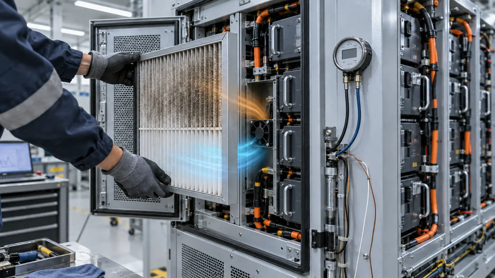
Filter loading is one of the quiet ways an air-cooled BESS cabinet loses thermal margin. The cells continue to charge and discharge, the fan may continue to report a normal RPM, and the controller may still show a healthy PWM command. Meanwhile the pressure drop across the intake has risen, the operating point has moved left on the fan P-Q curve and the modules furthest from the inlet may be receiving less useful air.
This is not only a filter problem. The loaded filter adds to grille, louvre, fan inlet, battery-module, cable and outlet losses. The complete cabinet system curve changes. If the fan was selected from free-air CFM or from a clean-bench test, the original number no longer describes the working condition. A maintenance plan must therefore be part of the cooling specification, not a document added after the cabinet is released.
ASHRAE material describes filter resistance as a value that should be monitored or used with an explicit replacement plan. That guidance is not a BESS acceptance limit. The transferable engineering rule is to define the actual service restriction, measure differential pressure at a named flow condition and prove that the battery temperature limit still holds at that condition.
This guide provides a practical method for BESS thermal engineers, cabinet designers and fan purchasers. The values in the examples are illustrative planning numbers. They are not universal filter thresholds or MEGA product ratings; each project must replace them with its own filter curve, heat load, environment and approved temperature limits.
How filter loading moves the fan operating point
The fan curve has not changed, but the cabinet resistance curve has.
For a first-order cabinet model, pressure drop often increases approximately with the square of flow: ΔP = k × Q². A loaded filter increases the effective k of the intake path. The fan still supplies the pressure described by its P-Q curve, but the intersection with the new system curve occurs at a lower airflow. This is why a fan can maintain a plausible speed while the battery modules receive less cooling air.
Consider an illustrative cabinet with a clean-path resistance of 70 Pa at 0.10 m3/s. If the loaded filter adds 45 Pa at the same reference flow, the total path is now 115 Pa before any other service change. A candidate fan that delivered the required flow at 70 Pa may deliver materially less at 115 Pa. The exact reduction must come from the actual fan curve and the measured cabinet path; it should not be guessed from the RPM display.
The measurement plane matters. A pressure tap immediately beside the fan may report fan pressure while missing a bypass route around the filter frame. A tap across only part of a pleated filter may miss a damaged seal. Define upstream and downstream locations, keep the probes away from high-velocity jets and record the filter face area, airflow condition and ambient state with every reading.
The pressure-drop budget guide gives a reusable method for listing each loss. For BESS, add battery-module distribution, rack gaps, service doors, weather louvres and any condensation or salt protection that changes the air path.

Define clean, loaded and failed service states
A maintenance threshold is useful only when every team can reproduce the condition.
The clean state should include a new filter, the final enclosure geometry, the intended louvre and the production fan sample. Record pressure drop across the filter and across the complete cabinet path if possible. Also record fan voltage, PWM command, RPM or FG feedback, current, inlet temperature, module temperatures and the hottest cell or power-electronics location.
The loaded state should not be described only as dirty. It can be defined by a pressure-drop value supplied by the filter manufacturer, a controlled test restriction that reproduces that value, a dust-loading protocol or a field service condition derived from site data. The chosen definition must be safe, repeatable and linked to the thermal acceptance test.
A failed or end-of-service state is a separate decision. It may be a maximum allowed differential pressure, a temperature-margin limit, an airflow alarm, a filter seal failure or a fan-control state with insufficient headroom. The cabinet team should decide what happens at that point: alarm and continue at reduced load, controlled shutdown, service request or another approved response. Do not infer the response from the fan supplier's PWM input.
A practical test matrix can use three rows: clean filter, representative service restriction and blocked or alarm state. It can use three operating columns: low load, rated load and the worst approved ambient. That matrix is more useful than a single headline CFM because it exposes when the fan, filter and control logic stop meeting the same requirement.
| State | Define it with | Evidence to record |
|---|---|---|
| Clean baseline | New filter and production enclosure | Filter ΔP, total path ΔP, airflow, RPM, temperatures |
| Representative loaded | Filter supplier curve or controlled restriction | Same measurements plus PWM headroom and noise |
| Maintenance threshold | Project-approved pressure or thermal limit | Alarm point, response time and service action |
| Failed or blocked | Safe fault injection or defined maximum state | Controller response and approved load reduction |
| Post-service | New filter, resealed frame and restart | Recovery pressure, thermal trend and alarm clear |
Do not let PWM hide a loaded filter
Speed control can recover some airflow, but it cannot create unlimited pressure margin or repair a bypass path.
A BESS controller may increase PWM command as temperature rises or as the filter differential pressure approaches a warning point. That can be useful, but it changes several things at once: fan current, acoustic output, auxiliary power and bearing duty increase. If the fan is already near the steep or unstable part of its curve, a higher command may produce less improvement than expected.
An illustrative control review might compare 40 percent, 60 percent and 80 percent command at the clean and loaded states. At each point record voltage, current, RPM, pressure, airflow evidence, inlet temperature, battery temperature and sound level. The percentages are only test points, not a universal BESS control schedule. The result should show where the fan still has useful headroom and where a maintenance action is better than more speed.
The controller also needs a distinction between filter loading and fan failure. A rising differential pressure with stable RPM suggests increasing system resistance. A falling RPM with stable pressure command may indicate voltage, connector, bearing or rotor trouble. A normal RPM with a low temperature difference can indicate bypass or a measurement problem. The alarm logic should use more than one signal where the risk justifies it.
The BESS fan control guide covers thermistors, PWM and FG feedback. For filter service, extend that logic with a pressure channel or a validated proxy. Never convert PWM percentage directly into airflow without a fan-and-cabinet calibration.
Check filter-frame sealing and airflow bypass
A low pressure drop can be a good result, or it can mean that air is avoiding the filter.
Filter loading analysis assumes that the air crosses the filter media. A poorly seated frame, damaged gasket or open service panel can allow air to short-circuit around it. The fan may then show a normal or even improved airflow signal while dust enters the cabinet and the cells receive an uneven distribution. In a BESS cabinet, a bypass route can also cause the pressure sensor to under-report the restriction that the modules actually experience.
Inspect the frame under the same thermal and vibration conditions expected in the field. Check gasket compression, door flatness, louvre attachment, fastener torque and any cable or pipe route that opens a parallel path. Use a smoke or tracer method only when it is compatible with the equipment safety plan, and do not introduce contamination into energized battery compartments.
Air distribution matters after the filter as well. A fan can push air into a large empty region while a battery rack behind a baffle receives little flow. Measure at several rack heights and module rows, and compare the hottest location rather than relying only on cabinet exhaust temperature. Computational fluid dynamics can identify likely recirculation, but the final acceptance should include a representative hardware measurement.
If the filter becomes more restrictive but the measured differential pressure stays unexpectedly low, investigate bypass before selecting a faster fan. A higher-speed fan can increase contamination and noise without solving the path that is actually limiting cell cooling.

Use differential pressure and temperature together
The maintenance decision should be based on the relationship between restriction, fan response and battery temperature.
A differential-pressure sensor is not an airflow meter. At a fixed geometry and a defined fan state, it can be a strong service indicator. When fan command or cabinet dampers change, the same pressure value may correspond to a different flow. Store the operating context with the reading: fan command, voltage, RPM, ambient temperature and load level.
Temperature is also a lagging signal. The hottest module may respond slowly after airflow falls, and a short charge or discharge pulse may not expose the same thermal gradient as a sustained rated load. Trend the temperature spread across representative cells or modules, not only the average exhaust temperature. The set of sensors should be justified by the thermal map and the control response time.
An illustrative alarm strategy can use a warning at a project-defined pressure increase, a confirmation timer to reject brief transients and a high-temperature action if the thermal limit continues to approach. The actual pressure and temperature thresholds must come from the filter curve, fan curve, cabinet test and battery supplier limits. Avoid copying HVAC final-resistance numbers into a BESS cabinet without checking face velocity and heat-load consequences.
After filter replacement, verify recovery. The pressure should return to the expected clean-state band, the fan should not remain at an unnecessary high command and the thermal trend should return to the approved envelope. If it does not, inspect the frame, louvre, fan direction, connector and module airflow distribution before clearing the alarm.
| Channel | Why it is needed | Typical question |
|---|---|---|
| Filter differential pressure | Shows resistance change at the chosen measurement plane | Has the intake path moved from the clean baseline? |
| Fan PWM and voltage | Provides the commanded duty and supply context | Is the controller asking for more recovery? |
| RPM or FG | Shows rotor response | Is the motor responding to the command? |
| Fan current | Shows electrical and mechanical loading | Is the fan consuming more power for less flow? |
| Inlet and module temperatures | Shows the thermal consequence | Is the temperature spread growing at rated load? |
| Load and ambient | Makes readings comparable | Did the operating condition change before the alarm? |
Representative engineering scenario
This anonymised scenario illustrates the review method, not a named customer claim or a guaranteed field result.
In a representative outdoor BESS cabinet review, a clean-filter prototype met the initial hotspot target during a short thermal run. The project team expected dusty deployment and wanted a maintenance action that would be visible before the hottest module reached its derating limit. The fan supplier received the cabinet envelope, filter curve, target voltage, PWM and FG interface, pressure-tap locations and the expected service condition.
MEGA Tech supplied an application-matched PWM fan sample with FG feedback, the agreed connector and cable routing. The team then measured the clean cabinet, a controlled loaded restriction and a post-service state using the final louvre, filter frame, battery-module layout and thermal load. The test record paired filter pressure with fan command, RPM, current and the hottest module temperatures.
The useful result was not a generic statement that the fan was stronger. It was a documented decision path: when resistance rose, how much PWM headroom remained, when the maintenance alert appeared, how quickly the thermal trend changed and whether the filter frame stayed sealed. If the loaded state had exceeded the thermal limit, the correct action would have been to change the filter, geometry, fan operating point or load strategy rather than conceal the problem with a catalogue airflow number.
This is the kind of evidence a production team can hand to commissioning and service personnel. It also gives a custom fan supplier a clear target for the next sample instead of asking for a larger frame without a defined operating point.
How MEGA Tech can support the loaded BESS air path
A custom fan sample is most useful when the filter, cabinet and thermal acceptance condition are defined together.
MEGA Tech develops customized DC cooling fans around the installed airflow and pressure requirement. For a BESS cabinet, that may involve fan frame or thickness, airflow direction, PWM response, FG or RD feedback, connector and cable length, bearing configuration, mounting details, environmental protection or a replacement fan matched to the real cabinet duty. The selection starts from the working point, not from a free-air CFM headline or a frame-size comparison.
For a first review, provide the heat load, target airflow or pressure at that airflow, filter clean and loaded curves, louvre and grille details, cabinet drawing, battery-module layout, inlet temperature range, altitude if relevant, voltage tolerance, control interface, connector, noise target, service interval and sample acceptance criteria. A pressure map or a short thermal failure record is especially valuable when the problem appears only after filter loading.
We can support a small first build for an early-stage cabinet, a replacement sample for an installed fan or a production-oriented variant after the loaded operating point is validated. The customer team remains responsible for the battery limits, BMS logic, fire-safety design, emergency ventilation, filter qualification and final field approval.
Our boundary is deliberate: MEGA Tech supplies and customizes cooling fans and fan samples. We do not supply the filter media, HVAC coil, liquid loop, battery-management controller, cabinet safety system or emergency exhaust design. The fan must be approved as part of the complete BESS cabinet.
Engineer FAQ: BESS filters and fans
The useful maintenance rule is tied to the installed air path and thermal acceptance limit.
Q: Can PWM compensate for every dirty filter? A: No. It has limited pressure headroom and increases power and noise. Validate the operating point and hotspot at the agreed service condition.
Q: What should trigger filter service? A: Use a project-defined pressure or maintenance condition supported by the filter, cabinet and thermal evidence. Do not copy a universal interval.
Q: Does normal FG feedback prove airflow? A: No. It confirms rotor-speed feedback, not airflow through the battery modules. Pair it with pressure and temperature evidence.
Q: Why can a low filter pressure drop be suspicious? A: A damaged frame or open service path can let air bypass the media. Inspect sealing and compare the measured flow path with the design.
Q: Should the filter threshold be based on a single exhaust temperature? A: No. Use the hottest relevant module or cell region and the temperature spread at a defined load. Average exhaust temperature can hide local bypass.
Q: What can MEGA Tech review? A: Share the cabinet drawing, filter curve, target pressure or airflow, heat load, environment, voltage, PWM/FG interface, noise target and maintenance expectation.
Questions for a BESS filter-maintenance design review
Use these questions before freezing the fan, filter, cabinet and alarm requirements.
- What are the clean-filter pressure drop, representative loaded pressure drop and approved end-of-service condition?
- At which airflow, fan command, voltage and ambient condition are the pressure values measured?
- Where are the pressure taps, and how has filter-frame bypass been excluded?
- What fan operating point remains at the loaded state, and how much PWM and current headroom is available?
- Which module or cell region defines the thermal pass limit, and how is temperature spread recorded?
- What should happen when differential pressure rises, FG disappears, RPM falls or the hottest module approaches its limit?
- Does the post-service test prove that pressure, airflow, temperature and fan command recover?
- What information must be supplied to the custom fan manufacturer before the next sample is built?