
A European Vertical Farm Had a Layer-to-Layer Climate Problem
The farm was producing healthy crops at the supply side, but the lower racks repeatedly showed a different air speed, humidity and leaf-surface condition.
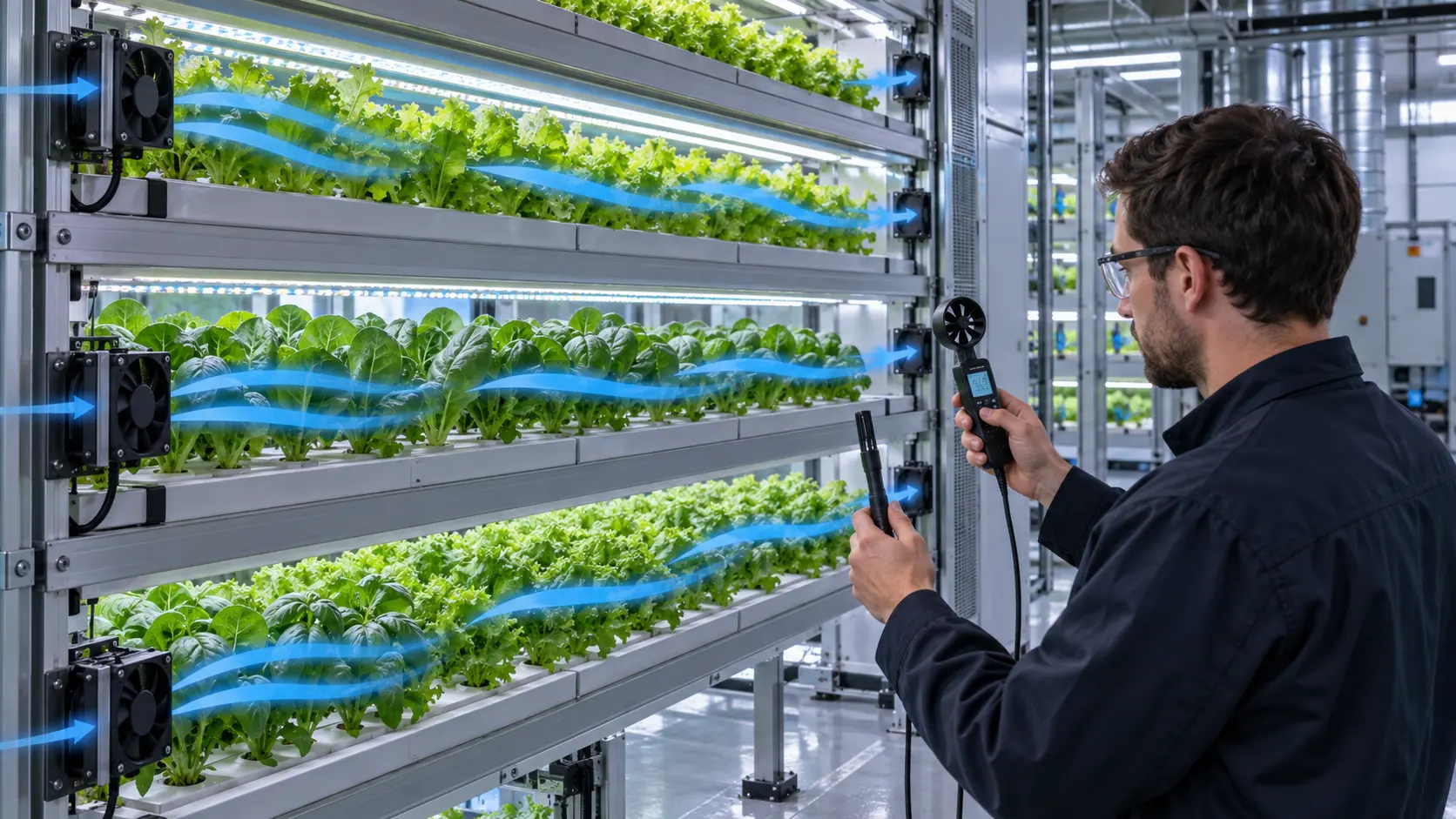
The anonymized European operator used stacked hydroponic racks with LED lighting and a central HVAC system. A commissioning check near the main supply looked acceptable, yet crop-zone measurements showed that the top layer received a stronger jet while the lower layers sat in a slower, wetter pocket. The problem was not simply too little total airflow; it was how the air was distributed after entering the rack bank.
The operator wanted a repeatable fan layout that could be installed without turning every shelf into a high-speed wind tunnel. The design had to balance air velocity, temperature, relative humidity, CO2 mixing, leaf comfort, electrical consumption and cleaning access. MEGA Tech was asked to review the physical rack sample and develop a small fan-and-baffle sample rather than recommend a catalogue fan from free-air CFM alone.
Customer identity and commercial crop data remain confidential. This case describes the engineering workflow, the measurements and the transferable decisions that matter when a vertical farm moves from a pilot rack to a repeatable production module.
Why Total Room Airflow Did Not Prove Crop-Zone Uniformity
A room can have enough HVAC capacity while individual leaves still experience different microclimates.
Research on vertical farms repeatedly treats temperature, relative humidity, CO2 and canopy air speed as a coupled uniformity problem. Multi-layer structures create obstacles, recirculation pockets and vertical stratification. A supply diffuser may deliver the intended flow to the aisle while the crop canopy receives much less or receives a short-circuit jet that exits before it crosses the leaves.
The operator's first control-room number was total air exchange. That number could not reveal whether the lowest crop layer was within the intended air-speed band. The commissioning plan was changed to record a grid at canopy height: several points across each shelf, at the inlet side, center and return side. The same locations were used before and after the layout change.
This distinction is important for fan selection. A larger fan can increase the top-layer jet and still leave the lower shelf under-mixed. A distributed, lower-speed fan layout with a defined return path can improve uniformity with less local turbulence. The correct choice depends on rack geometry and measured resistance.
The First Survey: Find the Fast Jet and the Wet Pocket
The team mapped the rack as a set of crop zones rather than averaging the entire room.
MEGA Tech and the operator logged air speed, dry-bulb temperature and relative humidity at canopy height. A handheld anemometer was used for the screening map, while fixed temperature and humidity sensors confirmed the trend over the operating cycle. The team also recorded light state, irrigation timing and door-opening events because those variables change the moisture load.
The first map showed a fast stream near the upper supply path and a slower pocket behind the lower shelf lip. The slow pocket also had a higher relative humidity after irrigation. That did not prove a disease event by itself, but it identified a location where condensation risk, leaf wetness and transpiration behavior deserved closer review.
A simple uniformity metric helped the discussion. If the mean canopy speed is 0.35 m/s and the standard deviation is 0.08 m/s, the coefficient of variation is CV = 0.08/0.35 = 23%. This is a screening example, not the customer's result. The point is to compare the same metric across layouts rather than rely on a hand-held impression.
| Variable | Where measured | Why it matters |
|---|---|---|
| Air speed | Canopy height, inlet, center and return | Shows stagnant pockets and excessive local jetting |
| Temperature | Leaf-zone air and rack exhaust | Separates lighting heat from mixing problems |
| Relative humidity | Same grid plus return path | Reveals moisture accumulation and dehumidification load |
| CO2 trend | Representative layers | Checks whether mixing reaches the crop |
| Fan command and current | Each circulation fan | Links uniformity to energy and control behavior |
Sample 01: Separate Global Delivery From Local Layer Mixing
The revised concept used the central HVAC system for room conditioning and smaller fans for the rack-scale distribution problem.
The first design decision was not to make the rack fans replace the HVAC system. The HVAC system still controlled room temperature, humidity and fresh-air conditions. The local fans were assigned a narrower job: move air through each crop layer, reduce recirculation behind the shelf, and mix the canopy without creating a damaging high-speed jet.
A vertical-farm CFD study published in 2026 similarly separates global air delivery from local layer mixing as two different design roles. That distinction is useful for product teams because the best fan for a rack shelf may not be the best fan for the room supply duct. It also makes the validation plan clearer: test the boundary condition first, then test the rack module.
The sample layout used fans at the side of selected layers with short baffles to guide the discharge across the canopy. The fan frame, outlet clearance, guard and cable route were kept serviceable. The design avoided placing a large fan directly above one crop zone, which would have produced a strong local jet and left adjacent plants dependent on diffusion.

Sample 02: Use Baffles and Return Paths Before Raising Fan RPM
Mechanical guidance changed the air distribution more efficiently than simply increasing every fan command.
The team compared an open shelf edge with a shallow baffle that directed part of the air along the layer. The baffle was not intended to seal the rack; it reduced the easiest short-circuit path from fan outlet to return. The operator could therefore use a moderate fan speed to reach the lower canopy instead of driving a high-speed stream at the upper shelf.
Published vertical-farm work has reported that separating growing layers with baffles can improve uniformity and moisture removal in a compact lateral-supply arrangement. Those results are geometry-specific, so they were treated as a design direction rather than copied as a guaranteed customer result. The sample was still measured on the real rack, with the actual crops, trays, lights and irrigation schedule.
The return path was checked as carefully as the supply. If exhaust air leaves from only one high opening, the lower layers may remain under-ventilated. The revised sample used a defined return side and checked pressure drop across the baffle, mesh, filter and rack opening. This is where a high-static-pressure fan can be useful, but only if the added pressure produces the intended layer flow.
Sample 03: Select the Fan for the Rack Resistance and Crop Duty
The fan candidate was selected around the measured path and operating schedule, not a free-air catalogue line.
The rack path included an inlet guard, a compact baffle, plant canopy resistance, a return grille and a washable screen. The fan had to start reliably at low speed, provide enough pressure for the loaded path and remain controllable during lighting and irrigation cycles. The customer compared a compact axial option with a higher-pressure variant because the same frame size did not guarantee the same installed flow.
A screening estimate made the energy trade-off visible. If six circulation fans each consume 2.5 W for 16 hours per day, their daily electrical use is 6 x 2.5 x 16 = 240 Wh/day, before controller losses. If a higher-pressure sample uses 4 W but allows two fewer fans, the comparison becomes 4 x 4 x 16 = 256 Wh/day. These are engineering examples, not customer data; the important point is to compare the complete layout, not fan wattage in isolation.
The final candidate was judged by canopy measurements, fan current, PWM response, acoustic behavior and maintenance access. A fan that meets airflow at the outlet but creates a high local velocity at the crop can be the wrong selection. A lower-speed distributed layout may create better uniformity and a more predictable climate response.
Validation: Temperature, Humidity and Air Speed Must Be Read Together
The revised layout was not accepted from a single air-speed reading.
The operator repeated the grid at the same canopy height under lighting on, irrigation active and steady-state conditions. The team recorded the fan command, RPM or FG feedback, current, inlet temperature, exhaust temperature and local relative humidity. Where a humidity pocket remained, the question was whether the cause was insufficient mixing, excess local moisture, sensor position or the room dehumidification boundary.
The design review also checked plant protection. Published controlled-environment agriculture research discusses canopy velocities around 0.3–0.5 m/s for lettuce-related studies, while other crops and growth stages can require different conditions. Those values should not be treated as universal fan setpoints. The crop, cultivar, leaf area, lighting, irrigation and growth stage define the acceptable band.
The result package included a measurement map and a repeatability note. If the rack pitch, tray depth, crop density, fan orientation, baffle or filter changes, the operator knows which parts of the validation must be repeated. That prevents a pilot result from being treated as a permanent guarantee after the physical geometry changes.
| Evidence | What it can show | What it cannot prove alone |
|---|---|---|
| Canopy air-speed grid | Layer uniformity and stagnant zones | Crop health or disease prevention by itself |
| Temperature and RH trend | Thermal and moisture response over a cycle | Correct fan selection without pressure data |
| Fan current and FG | Control stability and energy behavior | Adequate airflow if the path is bypassing |
| Visual smoke or particles | Short-circuit and recirculation path | Quantitative flow rate |
| Repeat test after irrigation | Moisture response and recovery | All seasonal operating conditions |
Result: The Farm Moved From More Air to Better Air
The customer received a repeatable rack module and a clearer rule for selecting fan count, pressure and control behavior.
The revised approach reduced dependence on a single strong top-layer jet. Each fan had a defined role, each layer had a measured supply and return path, and the acceptance test used the crop zone rather than the aisle as the reference. The operator could now compare fan command, air-speed CV, humidity recovery and energy use when deciding whether to scale the module.
The transferable lesson is that vertical-farm cooling is also a moisture and uniformity problem. More airflow can increase local turbulence, dry one shelf and leave another wet. More fans can increase energy and maintenance without fixing a short-circuit path. A measured baffle, return path and modest fan array can be a stronger engineering decision than a single larger fan.
MEGA Tech supported the project from the rack sample and crop-zone measurements through fan selection, interface adjustment and installed validation. The customer's agronomy team retained responsibility for crop setpoints and production acceptance; the fan design was judged by whether it made those setpoints more controllable.
How MEGA Tech Supports Vertical-Farm Fan Development
We help indoor-farming teams turn a rack geometry and crop-zone requirement into a testable fan layout.
MEGA Tech can review compact DC axial fans and custom fan arrays for multi-level racks, grow rooms, LED equipment bays and climate-control modules. The review can include frame and thickness, pressure-flow behavior, PWM, FG/RD, connector, cable exit, bearing option, humidity exposure, washdown concern, acoustic target and small-batch samples.
For a first review, send the rack section, shelf pitch, crop or tray type, light load, irrigation schedule, target air-speed band, temperature and RH limits, HVAC supply and return locations, fan envelope, voltage, control interface, maintenance condition and quantity. A small physical rack sample is especially useful because plants, trays, filters and baffles change the system curve.
We do not claim to replace the farm's HVAC, agronomy, food-safety or crop-validation responsibilities. Our role is to make the local fan path measurable and adjustable, then support a repeatable sample before production scale-up.
Engineer Questions About This Vertical-Farm Case
Use these questions before freezing a fan array or rack baffle.
Q: Is room-level airflow enough to accept a rack? A: No. Measure at canopy height across the actual layers because shelves and crops create local resistance and recirculation.
Q: Should every shelf have its own fan? A: Not always. Fan count depends on rack geometry, supply and return paths, crop resistance and the uniformity target.
Q: Can a larger fan solve a lower-layer wet pocket? A: It may increase the upper jet without reaching the lower layer. Check the path and baffle before raising RPM.
Q: What does MEGA Tech need for a sample? A: Rack section, shelf pitch, crop and tray geometry, HVAC boundary, air-speed target, RH and temperature limits, voltage, control interface and quantity.
Q: Are 0.3–0.5 m/s universal plant targets? A: No. Published lettuce studies provide useful reference bands, but crop, cultivar and growth stage must define the acceptance range.
Vertical-Farm Fan Design Review Checklist
A practical checklist for thermal, HVAC, agronomy and purchasing teams.
- What is the role of the rack fan: layer mixing, heat removal, humidity transport or CO2 distribution?
- Where are the supply and return paths, and can air short-circuit before reaching the crop?
- What is the target canopy air-speed band for this crop and growth stage?
- How will temperature, RH and air speed be measured at each layer?
- What pressure do guard, baffle, screen, tray and crop canopy add at target flow?
- Is the fan stable at low PWM and does FG feedback remain valid?
- How will irrigation, lighting, crop density and maintenance state change the duty?
- Has the layout been tested with the actual rack module rather than an empty frame?
- Which changes require a new grid test before the farm scales the design?
