The crop-zone problem
A multi-level hydroponic farm needed more than room-level temperature control. Each crop layer needed repeatable air movement across the canopy without turning the rack into a high-power fan wall.
The project covered a 4,500 sqm multi-level hydroponic facility growing butterhead lettuce, sweet basil and microgreens. The project team reported a 14% crop-loss level associated with tip burn and powdery mildew before the airflow layout was corrected.
This is a system problem as much as a fan problem. Dense shelves and crop canopies create resistance, while lights and plant transpiration add heat and moisture. A room sensor can show an acceptable average while individual layers still develop stagnant, warm or humid zones. Research on vertical farms similarly treats airflow distribution, temperature, relative humidity and leaf-level boundary-layer control as linked engineering variables rather than independent setpoints.
The target was therefore to move air through every rack module, improve the measured crop-zone velocity range and keep the fan platform compact enough for a repeatable shelf installation. The project did not use free-air CFM as the acceptance criterion; it used airflow measured in the installed rack arrangement.
- Application: multi-level hydroponic vertical farm.
- Facility area: 4,500 sqm, as reported for this project.
- Crops: butterhead lettuce, sweet basil and microgreens.
- Initial project-reported crop loss: 14%, associated with tip burn and powdery mildew.
Fan layout around the rack module
The practical change was to distribute compact fans at the rack level instead of relying only on room-level circulation.
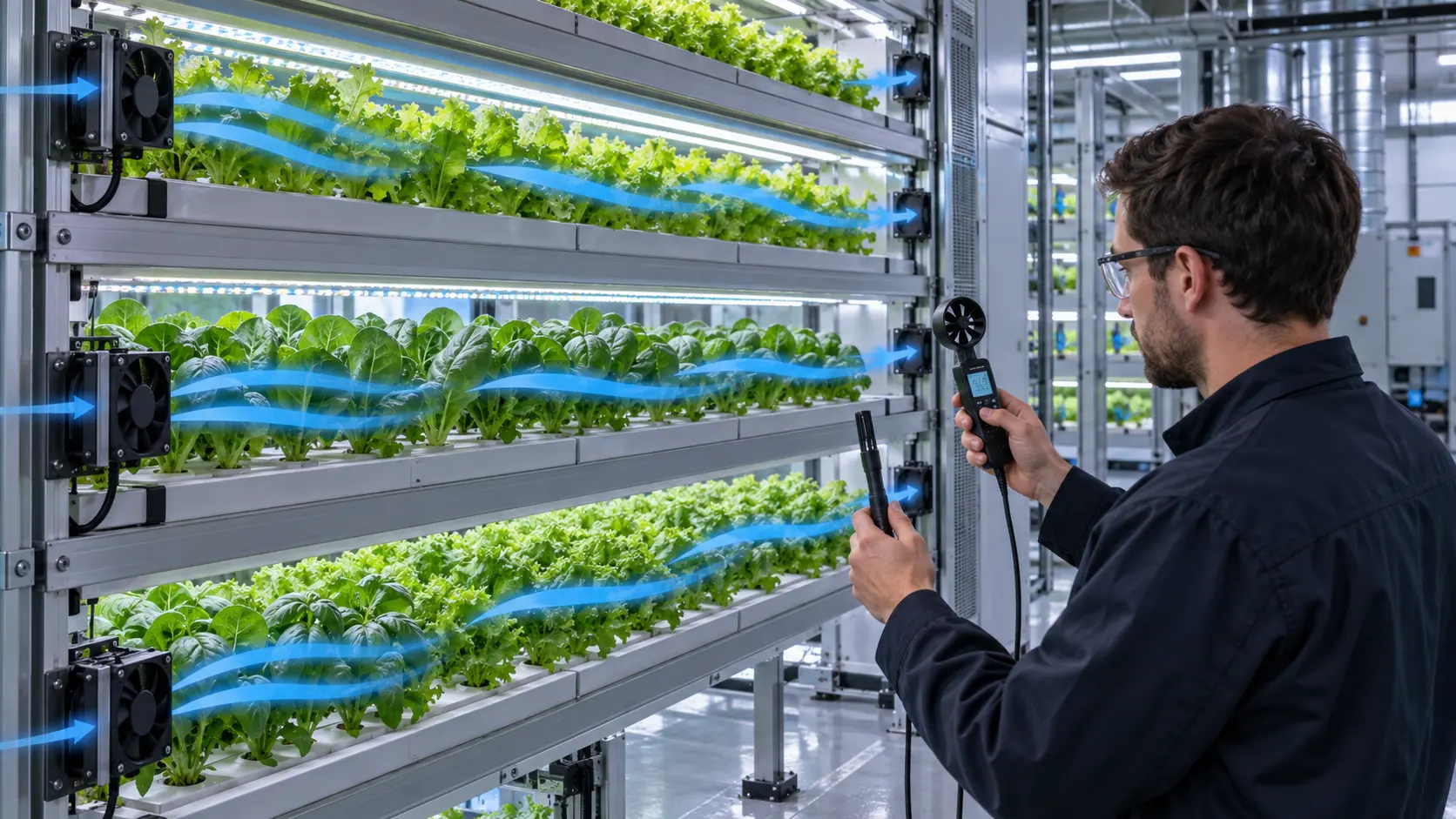
The approved concept used the 12 V MG8025H12X platform, with four fans installed on each 2.5 m rack module. The current catalogue row for this model lists 3,500 RPM, approximately 44.3 CFM and 5.3 mmH₂O at rated voltage. The project notes recorded approximately 42 CFM at the selected operating condition; that figure is treated as a project value, not substituted for the catalogue rating. The fan locations were selected to move air across the crop zone and reduce the chance that upper or enclosed layers would be served only by a distant HVAC discharge.
The exact fan speed and airflow must be selected against the installed rack resistance. Shelf depth, crop density, LED fixtures, guards, filters and adjacent modules all change the pressure loss. A catalogue airflow value is only a starting point; the useful number is the airflow and velocity that remain at the crop zone after the rack is populated.
The layout also leaves room for control refinement. A fan can be selected for the required voltage and space, then adjusted around the project's airflow, noise, connector, speed-control and service requirements. This matters in early-stage farm equipment, where shelf spacing and crop recipes can change during commissioning.

- Keep the airflow path across the canopy clear of avoidable short circuits.
- Check upper, middle and lower layers rather than measuring one representative shelf.
- Confirm fan speed, power and noise after the rack is populated.
- Leave access for cleaning, filter service and fan replacement.
Validation at the crop zone
The sample was judged by the environment the crop actually experienced, not by the fan nameplate alone.
The project team reported a crop-zone air-velocity range of 0.6-0.9 m/s after the MG8025 layout was installed. The measurement should be understood as project-specific: sensor position, crop stage, canopy density, rack geometry and fan command all affect the result.
The validation sequence should include air velocity at multiple shelf positions, temperature and relative humidity across the rack, day/night operation, different crop stages and the condition of the HVAC and dehumidification system. If the farm uses CO2 enrichment or variable lighting, those operating states should be included in the comparison because they change the heat and mass-transfer load.
For fan engineering, the acceptance record should also capture voltage at the fan, speed, current, noise, airflow direction and any control signal. That record makes it possible to distinguish a fan issue from an air-distribution issue when a crop layer later drifts out of uniformity.
- Measure air velocity at several points on every representative layer.
- Log temperature, relative humidity and VPD-related conditions with the airflow data.
- Repeat the comparison at different crop stages and day/night states.
- Record fan voltage, speed, current, noise and control response.
- Check the populated rack, not an empty shelf or open-bench fan test.
Project-reported result
The measured airflow improvement was associated with a large reduction in reported crop loss, but the result remains specific to this farm and operating recipe.
The project reported crop loss falling from 14% to 2.1%, a reported reduction of approximately 85%. It also reported a 1.5-day shorter growth cycle and a 12% net energy reduction, with the fan contribution recorded as 1.8 W per unit in the project data.
These are project-reported outcomes, not universal guarantees for every vertical farm. Crop variety, lighting schedule, nutrient recipe, HVAC duty, dehumidification, sanitation, plant density and measurement period can all change the result. Before using the figures for a new farm, reproduce the baseline and post-change measurement method under the new operating conditions.
The transferable result is the engineering method: distribute air at the rack, measure the canopy environment, check the fan at the installed resistance and then carry the approved configuration into repeatable production.
Engineer Questions About This Case
The case was judged by the crop-zone environment, not by the fan nameplate alone.
Q: Why was room-level circulation not enough? A: A multi-level rack can contain shelf-to-shelf dead zones even when room temperature looks acceptable. Each crop layer needs repeatable air movement across the canopy.
Q: What was the fan-layout approach? A: Compact fans were distributed at rack level instead of relying only on room circulation. The published configuration used four MG8025H12X fans per 2.5 m rack module.
Q: Which project values were reported? A: The project reported crop-zone air velocity of approximately 0.6 to 0.9 m/s on a 12 V, 3,500 RPM platform. Those values belong to the stated rack, layout and operating recipe.
Q: Why measure temperature, RH and VPD as well as velocity? A: Airflow changes heat and moisture transport. A velocity map without the climate variables can miss conditions that affect the crop zone and the control strategy.
Q: How should the layout be validated before rollout? A: Instrument a representative rack with the intended shelves, obstructions and control states, then compare spatial velocity and climate maps before freezing fan position, speed range and production acceptance points.
- Separate project-reported values from general engineering guidance.
- Record the test condition, mounting, voltage, speed and measurement method with every result.
- Use the case questions to define the next sample or validation step.
From a rack airflow issue to a repeatable fan solution
For a new vertical-farm module, MEGA Tech can review rack dimensions, crop-zone airflow, heat and humidity conditions, available fan space, voltage, noise and control requirements together. The development path can start with a small sample build, then move into rack testing before the approved fan configuration is released for repeat production.
The production handoff should freeze the fan model or customized configuration, installation spacing, connector and cable details, control range, measurement points and acceptance limits. This gives the farm equipment team a repeatable cooling baseline as the rack layout and crop program scale.
- Share the shelf dimensions, crop-zone target and available fan space.
- Define voltage, speed-control, noise, cleaning and service requirements.
- Build and test a sample in the populated rack module.
- Freeze the approved airflow layout and production inspection method.