The Robot Cell Passed Commissioning, Then Lost Thermal Margin
An anonymized European automation integrator needed to cool a robot controller cabinet installed beside a machining cell without pulling contaminated air across the electronics.
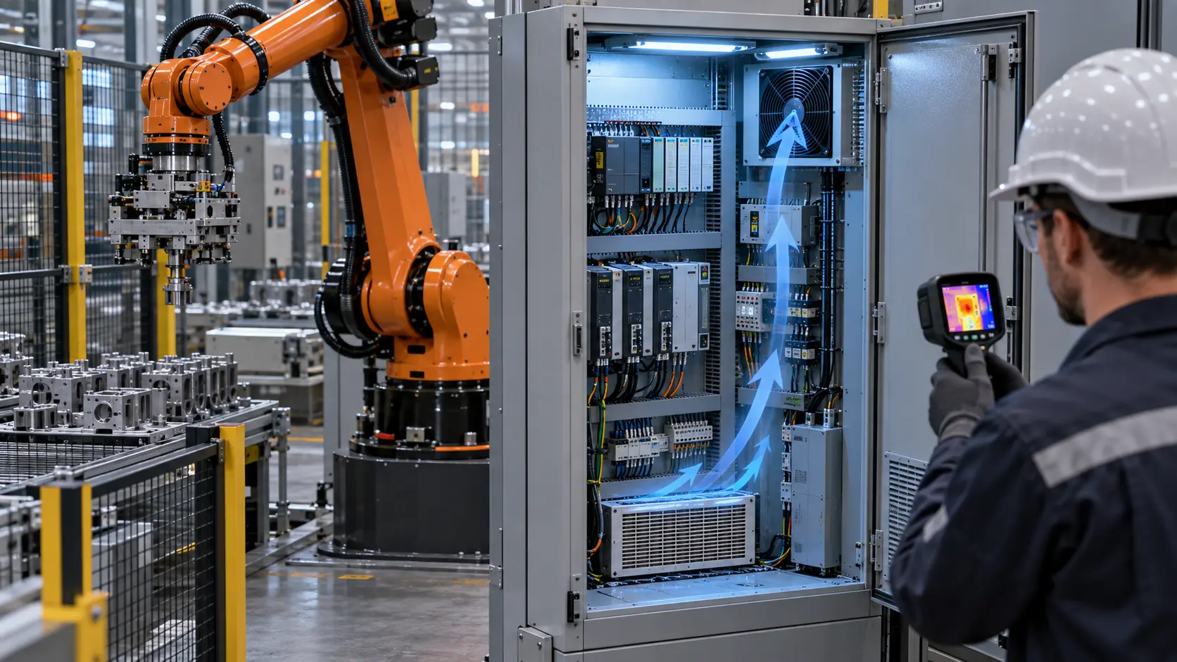
The robot itself was not the only thermal problem. The controller cabinet contained servo drives, a power supply, contactors and control electronics, while the surrounding cell added heat, airborne dust and intermittent production peaks. The cabinet passed an early commissioning check with a clean filter and open service conditions. After production began, the controller temperature rose during long motion cycles and the fan became noticeably louder.
The first request sounded simple: replace the fan with a higher-airflow model. The installed problem was more specific. The fan had to move air through a filter, grille, cabinet components and an upper exhaust path; it had to preserve the controller's voltage and feedback interface; and it had to keep dust outside the sensitive electronics. A higher free-air number could still fail if its pressure reserve disappeared across the loaded filter.
MEGA Tech reviewed the customer's cabinet sample, fan position, filter frame, heat-producing components and control signal. Customer identity and released production data remain confidential. This case describes the engineering workflow and the evidence that should be transferred into a production specification.
The Design Review Question: Where Does the Heat Actually Go?
A controller alarm is often treated as a fan problem before the cabinet heat load and air path have been separated.
The team first listed the heat sources instead of starting with a catalogue fan. Servo drives can dissipate differently during acceleration, deceleration and holding. Power supplies and contactors add a more continuous load. The robot's duty cycle matters because a cabinet that looks acceptable during a short jog may accumulate heat during an extended production sequence. Ambient air at the cabinet inlet and the air temperature at the upper exhaust were logged separately.
For a planning estimate, assume 420 W of cabinet heat and an allowable average air rise of 12 K. Using the common air-side approximation Qv = P/(rho x cp x deltaT), with air density about 1.2 kg/m3 and heat capacity about 1.0 kJ/(kg K), the required volume flow is roughly 0.029 m3/s, or about 62 CFM. That is not a release value: component hot spots, bypass, altitude, filter loading and non-uniform distribution can require more capacity.
A second estimate shows why margin matters. If filter loading and internal obstruction reduce useful flow from 62 CFM to 48 CFM while the heat load remains 420 W, the idealized average rise increases from about 12 K to about 15.5 K. The real cabinet can be worse because the hottest drive may not see the average air temperature. The acceptance test must therefore measure the limiting component, not only the exhaust air.
| Input | Why it changes the fan duty | Evidence to record |
|---|---|---|
| Heat load | Drive and power losses vary with robot cycle | Measured or documented loss by duty state |
| Ambient and altitude | Air density and inlet temperature change cooling capacity | Site maximum and test basis |
| Filter and grille | Pressure loss moves the fan operating point | Clean and loaded differential pressure |
| Cabinet layout | Blocked paths create local hot spots | Temperature grid and flow visualization |
| Control interface | PWM, voltage, FG and RD affect operation and alarms | Pinout, waveform, startup and fault log |
Interactive: See How Filter Loading Moves the Fan Duty
Switch between maintenance states to see why fan RPM alone cannot prove controller-cabinet airflow.
The schematic is qualitative, not a CFD result or a universal pressure multiplier. It structures the measurement plan: record the fan command, feedback speed, current, differential pressure and protected-component temperature for each state. A rising RPM with falling useful airflow can indicate that the controller is trying to recover pressure margin, not that the cabinet is receiving the required cooling.
For a first service rule, measure the clean-filter differential pressure and define a review point rather than waiting for a thermal alarm. The correct limit depends on the filter media, area, fan curve and cabinet path. A practical sample plan can test a clean filter, an intentionally loaded filter that represents the maintenance limit and a reduced-speed or fault state.

Sample 01: Rebuild the Cabinet Air Path Before Changing the Fan
The first sample kept the fan frame and controller interface visible while making the pressure path measurable.
The customer supplied the cabinet section, current fan, filter frame, grille, controller connector and the positions of the servo drives. MEGA Tech mapped the intended path from filtered intake to the upper exhaust and checked whether the fan discharge actually crossed the heat sources. A fan placed low in the cabinet can work well when the discharge rises through the drive stack, but a side obstruction or a short-circuit gap can send most of the air directly to the outlet.
The first candidate was not selected from maximum CFM. The review considered frame and thickness, pressure-flow behavior, 24 V tolerance, startup current, PWM or voltage control, FG/RD feedback, connector and cable exit, bearing option, temperature range and acoustic target. The sample used the customer's mounting and filter rather than a free-air bench setup alone.
The team recorded fan command, RPM, current, differential pressure across the filter, cabinet inlet temperature, exhaust temperature and the hottest drive temperature. This created a baseline that procurement could understand: the comparison was between two installed configurations, not between two marketing numbers.
Sample 02: Compare Clean, Loaded and Peak Robot Duty
The candidate fan was accepted only after the cabinet was tested in the states that could cause a field alarm.
The clean-filter run established the best-case airflow path. The loaded-filter run represented the maintenance boundary agreed with the integrator, not an arbitrary blocked panel. The peak robot-duty run combined the highest expected servo activity with the highest declared ambient. A warm restart was added because a fan that starts reliably at room temperature may behave differently when the cabinet and motor are already warm.
The test log kept the original and candidate fan on the same voltage, command, filter, grille, cabinet door and measurement positions. The useful comparison included the temperature rise of the limiting drive, not only the average cabinet air. It also included power input and sound because a high command can recover temperature while increasing cabinet noise and electrical consumption.
An illustrative acceptance table might define a maximum drive temperature, a maximum filter differential pressure for service, a minimum stable fan command, an FG fault response and a restart requirement. The actual numbers belong to the robot-controller and enclosure design owner. MEGA Tech's role is to make the fan-side evidence repeatable around those declared conditions.
Sample 03: Keep the Controller Interface Stable
A thermal improvement is not production-ready if it creates a connector, alarm or control-logic change that the machine team has not tested.
Robot controllers commonly operate inside a larger machine-control architecture. The replacement fan therefore had to preserve the declared supply range and connector arrangement while making its control behavior explicit. The review covered minimum startup voltage, PWM level and frequency where applicable, FG pulse behavior, RD or locked-rotor indication, current during startup and the controller's response when feedback disappeared.
The fan's speed signal was treated as evidence of rotor motion, not proof of airflow through the filter and drives. A normal RPM value can coexist with a bypass leak, a detached filter or a blocked discharge. The production record therefore paired feedback with differential pressure and a thermal measurement at the critical drive.
This is also where customisation can be valuable for a smaller automation company. A supplier can adjust the fan sample, cable exit, connector, control curve and mounting details around the customer's cabinet rather than forcing the prototype to accept a catalogue part that only fits dimensionally.
| Item | MEGA Tech can support | Machine builder must validate |
|---|---|---|
| Fan sample | Frame, thickness, motor, bearing and airflow direction | Fit, guarding and robot-cell safety |
| Control | PWM, voltage, FG/RD and startup behavior | PLC or controller logic and alarm response |
| Air path | Fan-side pressure-flow data and sample tuning | Cabinet, filter, grille and component distribution |
| Environment | Declared fan temperature and sample condition | Ingress, dust, chemical exposure and enclosure rating |
| Reliability | Fan construction and declared test evidence | Complete controller, machine duty and service plan |
Validation: Temperature Maps Are More Useful Than One Exhaust Reading
A robot cabinet can have a comfortable exhaust temperature while a drive or power supply remains above its preferred operating margin.
The final sample run used a temperature map around the likely hot spots: drive heat sinks, power supply, contactors, controller inlet and upper exhaust. The map was repeated at steady production duty and after the cabinet had warmed. If a thermocouple or infrared camera was used, emissivity and measurement position were documented; an infrared image is useful for locating a pattern but is not automatically a calibrated component temperature.
Airflow checks were performed at the filter, fan outlet and critical component path. Smoke or particle visualization can show recirculation and bypass, but it does not replace a flow measurement. A differential-pressure reading can reveal filter loading, but it does not prove that the critical drive receives uniform air. These measurements answer different questions and should stay separate in the report.
The resulting test record tied each result to a sample revision, filter state, voltage, fan command, robot duty and ambient condition. That detail matters when the cabinet layout changes, a new drive is added or the filter supplier changes media. Without it, a passing prototype can become an unexplained field failure.
Result: A Serviceable Fan Margin Replaced a Catalogue Guess
The integrator received a sample configuration and a maintenance-oriented validation method rather than a larger fan selected from free-air CFM.
The final engineering package described the installed pressure and airflow reference, filter condition, fan command, feedback behavior, connector, cable exit, mounting and temperature measurement points. It also recorded the boundary between normal cooling and a fault state. This gave the machine team a basis for deciding when a filter needed service and when a fan alarm required an immediate stop or controlled derating.
The case does not claim that one fan or one filter architecture is correct for every robot controller. A dusty machining cell, a clean assembly line and a sealed cabinet have different environmental and thermal requirements. The useful result is the method: start with the customer's physical sample, identify the heat and contamination boundary, measure the installed pressure path, tune the fan and control behavior, then validate the real duty cycle.
MEGA Tech supported the project from the customer sample through fan selection, interface review, filter-path testing and production-representative sample evaluation. The integrator retained responsibility for the robot controller, cabinet rating, electrical safety, machine risk assessment and final production approval.
How MEGA Tech Supports Robot-Control Cabinet Fan Customization
We develop the fan around the cabinet's real heat load, filter condition, pressure path, control interface and production constraints.
MEGA Tech can review custom DC axial fans and compact centrifugal blowers for robot controllers, servo cabinets, PLC panels, machine tools and industrial automation equipment. The review can include frame and thickness, pressure-flow behavior, airflow direction, connector and cable exit, PWM or voltage control, FG/RD feedback, bearing configuration, startup, temperature range, noise, vibration and small-batch sample development.
For a useful first review, provide the cabinet or prototype, heat-loss estimate by duty state, ambient and altitude basis, fan envelope, filter and grille details, target airflow at pressure if known, voltage tolerance, control interface, connector pinout, noise limit, service interval, life assumption and expected quantity. A short video of the alarm or a photograph of the filter and hot spot can be more useful than a part number by itself.
We do not supply the robot controller, PLC, servo drives, cabinet air conditioner, filter certification, machine safety system or final enclosure approval. We provide the custom fan engineering, sample revisions and fan-side evidence needed by the responsible automation team to complete system validation.
Engineer Questions About This Robot-Controller Case
These questions help separate a fan replacement request from a complete cabinet cooling requirement.
Q: Does a higher CFM fan automatically solve controller overheating? A: No. The fan must deliver useful airflow at the loaded filter and cabinet pressure, and the critical component must be measured.
Q: Should a dusty cabinet always be sealed? A: Not always. Compare filtered open-loop ventilation, sealed air-to-air exchange and air conditioning against heat load, contamination, condensation, service and safety requirements.
Q: Does normal RPM prove that the drive receives enough cooling? A: No. Pair fan feedback with pressure, airflow-path checks and component temperature.
Q: Why test the loaded filter instead of only the clean filter? A: Filter restriction moves the fan operating point and can reduce useful airflow before a thermal alarm appears.
Q: Can MEGA Tech choose the final cabinet filter and safety rating? A: We can review the fan and sample around the declared filter path, but the machine builder owns the complete environmental, electrical and safety decision.
Q: What should we send for a first sample review? A: The cabinet or section, heat load, ambient, filter, fan envelope, voltage, control signal, connector, target pressure or airflow, noise limit, duty cycle and quantity.
Questions for a Robot-Control Cabinet Fan Design Review
Use this checklist before approving a replacement or customised fan for an industrial robot cell.
- What are the continuous and peak heat losses of the drives, power supply and controls?
- What ambient temperature, altitude and production duty define the worst case?
- Is the cabinet open-loop filtered, sealed with an air-to-air exchanger or air-conditioned?
- What pressure drop is measured across the clean and maintenance-limit filter?
- Does the fan operating point remain inside its stable pressure-flow region?
- Which component is the thermal bottleneck, and where is its temperature measured?
- Are fan voltage, PWM, FG/RD, connector and startup conditions frozen?
- What happens after a fan fault, feedback loss, filter alarm or warm restart?
- Were cable routing, grille clearance, service access and vibration checked on the real cabinet?
- Which values are measured, which are planning estimates and which belong to the machine builder's approval?