The AMR Lost Runtime Before It Lost Battery Capacity
An anonymized European warehouse-robot developer needed to cool a battery and control compartment without spending the robot's limited energy on an oversized fan.
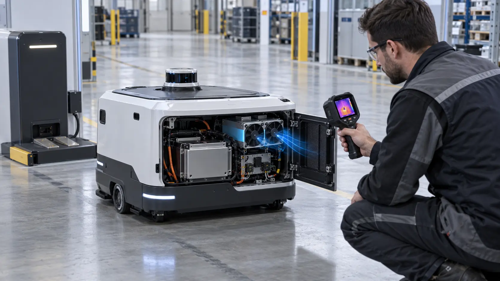
The mobile robot operated repeated pick-and-place routes, returned to a charging dock and then resumed work. During short tests, the battery pack, motor controller and edge-compute electronics stayed within the expected temperature band. During long routes in a warm warehouse, the controller reduced output and the robot required an earlier charging interval. The fan was running, but the team did not know how much useful air reached the heat sources.
The first proposal was to increase fan size. That would have changed mass, acoustic behavior, current draw and the internal duct. The real requirement was to separate three duties: remove heat from the battery area, protect the controller and power electronics, and preserve autonomy by limiting cooling parasitic power. MEGA Tech reviewed the customer's AMR sample and developed a fan-and-duct sample around the actual compartment.
The customer identity and released battery data remain confidential. This case presents the engineering workflow, illustrative calculations and validation questions that matter when an AMR moves from a prototype to a repeatable fleet product.
The Engineering Hook: Cooling Power Comes From the Same Battery
A mobile robot fan must protect the thermal system without quietly reducing the energy available for motion and payload work.
The team estimated heat by operating state rather than using one nameplate value. Traction and lift drives produced short peaks during acceleration and lifting. The compute module and DC-DC converter produced a more persistent load. Battery heat depended on current, ambient temperature, charge state and the route profile. The cooling fan itself also consumed battery energy, so the design needed a thermal benefit per watt.
As an illustrative estimate, suppose the compartment must reject 180 W and the allowable average air rise is 10 K. Using Qv = P/(rho x cp x deltaT), with air density about 1.2 kg/m3 and heat capacity about 1.0 kJ/(kg K), the ideal flow is about 0.015 m3/s, or 32 CFM. If the real duct and filter reduce useful flow to 24 CFM, the same simplified estimate rises to about 13.3 K. Those values are planning estimates, not battery or controller limits; the manufacturer must measure the hot spot and the cell temperature spread.
A second comparison considered fan power. A 24 V fan drawing 0.35 A uses about 8.4 W at full command. If control keeps it at 0.18 A for most of a route, the electrical input is about 4.3 W. The saved 4.1 W is small beside traction power, but it accumulates across long shifts and fleets. The fan must therefore be selected at the installed operating point, with a control strategy that does not hunt unnecessarily.
Airflow Layout Decided the Battery Temperature Spread
Battery airflow is not only a total-flow problem: inlet and outlet positions, cell arrangement and channel resistance determine which region receives the coolest air.
Research on air thermal management for autonomous mobile robots emphasizes that cell arrangement and inlet/outlet position change the flow characteristics. It also reports that air warms as it passes through a pack, so downstream cells can become hotter unless the manifold or channel layout redistributes the air. The review further notes that fan placement behind a battery can be more favorable than a side position in some layouts, but the result remains geometry-specific.
The customer sample had a short side inlet and a long battery channel. The first fan placement delivered a strong jet near the inlet and weaker flow toward the far cells and controller board. Moving the fan was not sufficient by itself because the duct, grille and service panel changed the pressure loss. The sample revision used a short plenum and a measured return path so the fan's pressure was spent across the intended load rather than a bypass gap.
The design objective was not to promise a universal cell temperature difference. It was to make the temperature map repeatable: same route, same state of charge, same inlet temperature, same fan command and the same measurement points before comparing a new sample.
| Input | Why it matters | Evidence |
|---|---|---|
| Route and duty | Drive peaks and compute load vary with motion | representative route log |
| Battery layout | Channel resistance sets cell-to-cell airflow | pack drawing and flow map |
| Fan power | Cooling consumes the same energy as autonomy | voltage, current and command |
| Vibration and tilt | Clearance and flow distribution can change in motion | motion test and mounting review |
| Service environment | Dust and dock debris load filters and grilles | clean and maintenance-limit states |
Interactive: Watch Route Duty and Charging Duty Use Different Fan States
The animated schematic separates a moving route from a high-current charging state so the fan is not selected from one average condition.
The figure is qualitative, not a CFD result. It shows why the same fan command may be unnecessary during a low-load route and insufficient during charging or a high-current mission. A production controller may use temperature, current, charge state or a combination, but the fan sample must be checked against the available signal and startup behavior.
The test plan used at least four states: idle, representative route, peak route and charging. Each state recorded battery temperature at multiple positions, controller temperature, inlet temperature, fan command, RPM or FG, current and acoustic behavior. If a filter is used, differential pressure was recorded as a separate variable.

Sample 01: Start With the Physical Robot, Not the Part Number
A compact fan that fits the drawing can still fail when the robot moves, tilts, charges or returns to a dock.
The integrator supplied the robot shell, battery compartment, controller board, fan envelope, duct section, grille, connector and cable route. MEGA Tech reviewed axial and compact centrifugal options against the available pressure, flow direction, thickness, voltage range, control method, FG/RD requirement, bearing option and quantity. The sample was not judged by free-air CFM alone.
The mechanical review included wheel and service-panel clearance, cable movement, fan guard, filter access and the effect of the charging dock. A dock can add heat near the intake, while a robot that reverses direction or passes close to a wall can see a changed inlet condition. These details are part of the installed duty and should be reproduced before a production sample is frozen.
For a small first build, the customer can learn more from two or three controlled fan revisions than from a large catalogue comparison. The objective is to isolate whether the limiting factor is fan pressure, duct geometry, battery arrangement, control behavior or mounting.
Sample 02: Tune Cooling Against Autonomy and Noise
The candidate sample was evaluated as a thermal-energy tradeoff, not only as a maximum-temperature test.
The first revision recovered airflow at the far end of the compartment but increased current at the highest command. The team then adjusted the duct transition and tested a lower steady command during the normal route. A minimum speed was retained for electronics protection, while a higher command was reserved for peak route and charging states. Hysteresis prevented rapid command changes when temperature hovered around a threshold.
The acoustic test was performed beside the charging area and during representative motion. A robot may be acceptable in an empty factory but objectionable near operators or at a docking station. The report separated broadband airflow noise, blade or motor tone, vibration transferred through the shell and wheel or drivetrain noise. A quieter fan on a bench was not automatically a quieter installed robot.
The final control decision remained the robot maker's responsibility. MEGA Tech provided fan-side response data and sample behavior so the integrator could choose a command curve consistent with battery autonomy, thermal margin and user environment.
Sample 03: Validate Vibration, Tilt and Warm Restart
A mobile platform exposes failures that a stationary fan bench cannot reveal.
The sample was tested on the actual bracket through representative motion, tilt and warm restart conditions. The team checked impeller clearance, bracket flex, cable retention, connector strain, abnormal noise, feedback dropout and current spikes. The goal was not to claim that one laboratory motion sequence represents every warehouse floor; it was to expose the interfaces most likely to fail after the robot leaves the bench.
Warm restart mattered because the fan, electronics and battery compartment were already hot when the robot returned from a route or docked after a peak event. The minimum declared voltage was checked, along with the controller's response when the fan failed to start or the FG signal disappeared. A fan that spins at nominal voltage but fails during a warm low-voltage restart is not production-ready.
The customer also inspected service access. A filter, guard or fan that cannot be cleaned without removing the battery may turn a good thermal design into a poor fleet-maintenance design.
Validation: Map Temperature Spread, Not Just the Hottest Point
The AMR needed both a safe maximum temperature and a repeatable temperature distribution across the battery and electronics.
The acceptance map included battery inlet-side cells, middle cells, outlet-side cells, the controller heat sink, DC-DC converter, fan inlet and compartment exhaust. The same route and charge state were repeated after the robot reached steady temperature. The report recorded ambient, state of charge, current, speed, payload, fan command and measurement uncertainty.
If the battery temperature spread was large, the next design question was airflow distribution rather than simply more CFM. A bypass gap, short-circuit path or uneven channel can leave one region hot while the average exhaust looks acceptable. Smoke or particle visualization can reveal a path; it cannot replace a measured temperature map or pressure check.
The production record separated measured results from estimates. This prevented a planning calculation such as 32 CFM from becoming a promised battery-performance number without the cell chemistry, pack design, route and ambient basis.
Result: A Custom Sample Protected Thermal Margin Without Hiding the Energy Cost
The integrator received a fan, duct and control configuration that could be tested against route, charging and maintenance states.
The final package defined the fan envelope, airflow direction, installed pressure reference, voltage tolerance, control signal, FG/RD behavior, current by state, mounting, cable route, filter condition and measurement map. It also recorded which command states were intended for idle, route, peak route and charging. This was more useful to procurement than a single maximum airflow number.
The transferable lesson is that mobile-robot cooling is a coupled design problem. Battery layout, controller placement, duct resistance, fan power, vibration, dust, noise and service access all influence the result. More airflow can improve a hot spot while reducing autonomy or increasing acoustic disturbance; a smaller customized sample may be the better system choice if the path is corrected.
MEGA Tech supported the project from the customer's physical AMR sample through fan selection, duct and control adjustment, vibration checks and installed validation. The robot maker retained responsibility for battery safety, BMS logic, charging approval, robot performance and fleet release.
How MEGA Tech Supports AMR and Mobile-Robot Fan Customization
We develop the fan around the real mobile platform, not an isolated battery or controller datasheet.
MEGA Tech can review custom DC axial fans and compact centrifugal blowers for AMR battery compartments, motor controllers, edge-compute modules, charging electronics and service-robot enclosures. The review can include frame and thickness, pressure-flow behavior, airflow direction, connector and cable exit, PWM or voltage control, FG/RD feedback, bearing configuration, startup, temperature range, noise, vibration and small-batch sample development.
For a first review, provide the robot sample or section drawing, battery and electronics heat load by state, ambient and charging conditions, fan envelope, duct and grille, filter or dust requirement, target airflow at pressure, voltage tolerance, control interface, connector, acoustic target, vibration condition, service interval and expected quantity. A short route log and a thermal image of the failure state are valuable starting evidence.
We do not supply the battery cells, BMS, charger, robot controller, drive system, enclosure safety approval or fleet certification. We provide the custom fan engineering, sample revisions and fan-side evidence required by the responsible mobile-robot team to complete system validation.
Engineer Questions About This AMR Cooling Case
Use these questions to prevent a mobile-robot fan quote from hiding the real thermal and energy constraints.
Q: Does more fan airflow always improve AMR runtime? A: No. Fan power consumes battery energy, and a stronger fan may not improve the limiting path if the duct or battery layout bypasses the flow.
Q: Should the battery and controller use one fan? A: Only after their temperature, contamination, pressure and control requirements are shown to be compatible. Separate paths can make the acceptance test clearer.
Q: Why test charging separately from driving? A: Charging can create a different heat load, dock environment and fan command than a normal route.
Q: Does normal RPM prove the battery is cooled evenly? A: No. Measure the temperature map and the actual air path; feedback proves rotor motion, not cell-to-cell distribution.
Q: Can MEGA Tech specify the battery safety limit? A: No. We can support the fan sample and measurements, but the robot maker and battery team own cell, BMS and charging approval.
Q: What should we send for a first review? A: The robot section, heat load by state, battery layout, fan envelope, duct, voltage, control signal, dust condition, route profile, noise target and quantity.
Questions for an AMR Fan Design Review
Use this checklist before freezing a cooling fan for an autonomous mobile robot or warehouse vehicle.
- What are the battery, drive, compute and charging heat loads in each operating state?
- What ambient, state-of-charge, payload and route define the worst case?
- Where are the battery inlet, outlet, controller and fan located relative to one another?
- What airflow and static pressure are required at the real duct, grille and filter?
- How much electrical power may the cooling fan consume during a full shift?
- Were temperature spread, hot spot, fan current and feedback logged together?
- Were motion, tilt, vibration, warm restart and minimum-voltage startup tested?
- What happens after a fan fault, feedback loss, blocked filter or high-temperature event?
- Can the operator service the fan or filter without unsafe battery access?
- Which values are measured, which are estimates and which belong to the battery and robot approval process?