The Printer Sample Had Three Different Cooling Problems
A 3D-printer customer came with a working prototype, but the fan problem could not be solved by increasing one RPM value.
The customer was developing an enclosed FDM printer for both general-purpose and engineering materials. The prototype could print short parts, but long jobs exposed three different symptoms: occasional heat creep near the hot end, uneven cooling on bridges and overhangs, and an enclosure temperature that changed too much between the front and rear of the chamber. The first reaction was to look for a stronger fan. The engineering review showed that the printer had three cooling duties with different objectives.
The hotend fan had to keep heat from travelling up the heat break and softening filament too early. The part-cooling fan had to deliver a balanced jet through a printed duct without cooling the heater block or creating excessive noise. The chamber airflow had to manage heat soak and material-specific conditions without destroying the stable temperature needed for ABS, ASA, nylon or other engineering materials. Treating these as one fan-selection problem would make the prototype less predictable.
MEGA Tech used the customer's printer, toolhead, duct and enclosure as the starting point. The goal was not to claim a universal fan upgrade. It was to develop a sample that matched the actual interface and then adjust the fan, control curve and airflow path until the customer's test record became repeatable.
What the 3D-Printing Engineers Needed to Balance
The requirement was defined by print material, thermal zone, airflow path, noise and control response together.
The first question was material mode. PLA and some PETG jobs can be sensitive to excessive chamber heat and to weak hotend heat-sink cooling. ABS, ASA, nylon and other engineering materials can need a warmer, more stable chamber to reduce warping and layer-stress problems. The correct chamber airflow is therefore not simply maximum exhaust. It depends on the material profile, the printer's enclosure and the target chamber condition.
The second question was where the air had to go. A hotend fan is judged by heat-sink temperature and heat-creep margin. A part-cooling fan is judged by air distribution at the nozzle and new layer. A chamber fan is judged by mixing, temperature uniformity, heat-soak time and controlled exhaust. A high-pressure blower may suit a restrictive printed duct, while an axial fan may suit a larger open path. The P-Q curve and installed resistance must be considered for each loop.
The third question was mechanical and acoustic. The toolhead has limited mass and moving cable space. The fan must fit the mount, survive repeated acceleration, avoid resonance and keep the sound acceptable during long prints. A lower-voltage rail or PWM output may also limit the available operating range. These constraints are why the first customer sample is more valuable than a generic CFM comparison.
| Cooling duty | Primary evidence | Typical design risk |
|---|---|---|
| Hotend | heat-sink temperature, startup and heat-creep margin | filament softens too early or the nozzle path clogs |
| Part cooling | left/right airflow, duct pressure and layer result | overhangs vary or the heater block is cooled |
| Chamber | temperature map, heat-soak time and exhaust state | material mode becomes unstable |
| Toolhead mechanics | mass, cable clearance, vibration and resonance | print artifacts or premature fan failure |
| Control | PWM/voltage response, minimum speed and restart | fan stalls, hunts or cannot recover |
Sample 01: A Bigger Fan Did Not Fix the Print
The first prototype showed why a fan with more free-air flow can still produce a poor result in a printed duct.
The customer's baseline toolhead used a compact blower feeding a narrow, printed shroud. The fan sounded acceptable in free air, but the pressure loss through the shroud changed the operating point. One side of the nozzle received a stronger jet than the other. At the same time, the hotend heat sink saw a warmer inlet when the enclosure was closed. The print symptom looked like a part-cooling problem, but the thermal state of the hotend was also moving.
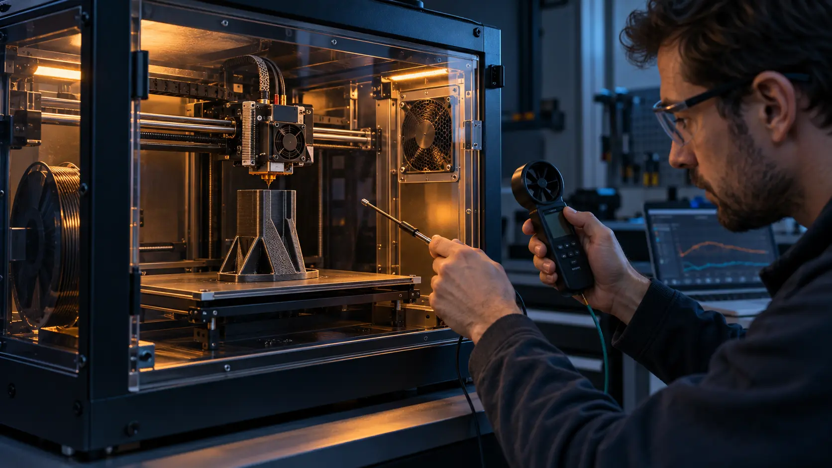
The first test separated the three loops. The team recorded fan voltage, command, RPM, current, inlet temperature, pressure or airflow proxy, heat-sink temperature and a local temperature map around the nozzle. It then printed a controlled bridge and overhang coupon in the selected material. The purpose was not to use print quality as the only thermal measurement; it was to correlate a visible result with the airflow and temperature evidence.
An illustrative calculation framed the design review: if the hotend heat sink must reject 6 W with a 20 °C allowed rise, the required air-side performance depends on the heat-sink resistance and the actual inlet temperature. If the enclosed chamber raises the inlet by 12 °C, the same fan and heat sink have less margin before the filament path becomes vulnerable. These are planning values, not a customer result. The sample needed an improved path, not simply a larger number on the fan label.
Sample 02: Tune the Duct and Fan Together
The second revision focused on balanced flow at the nozzle while protecting the heater and keeping the moving toolhead practical.
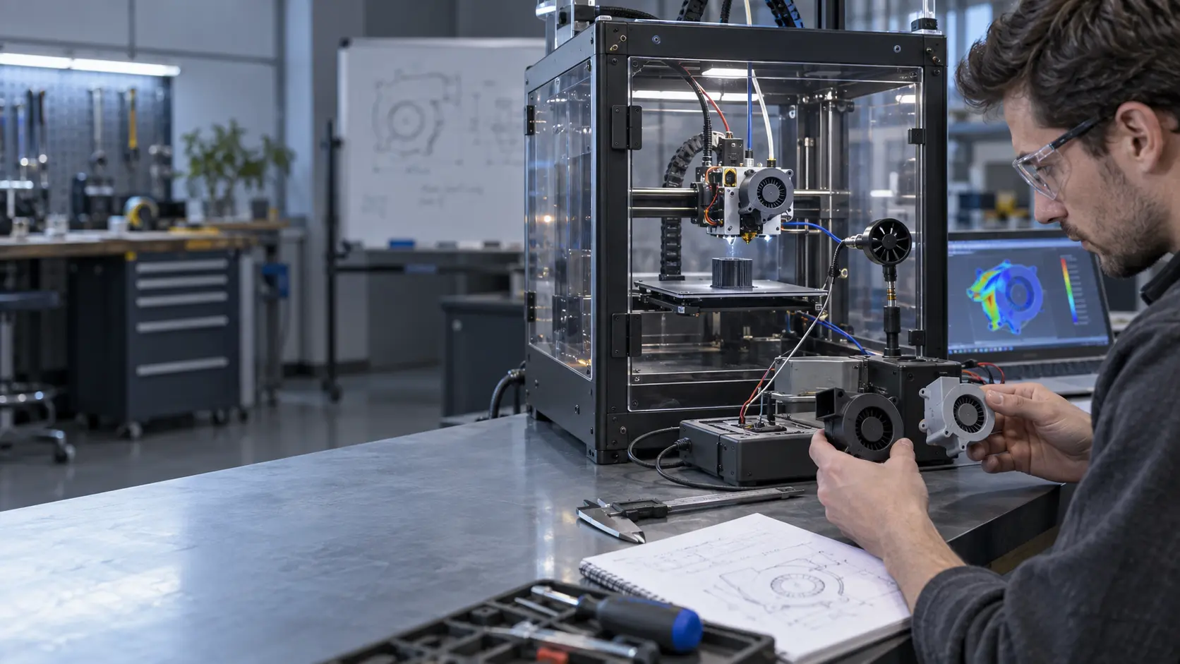
MEGA Tech reviewed the fan envelope, duct throat, outlet angle, clearance to the heater block and the toolhead mounting points. The sample was adjusted so that the fan worked against the real duct resistance rather than an open-air condition. The outlet geometry was refined to reduce a direct jet onto the heater block and to improve left/right balance at the layer. The exact geometry remained the customer's design decision; the fan sample was evaluated in that geometry.
The control curve was also changed. At low print speed, the part fan did not need to run at the same command as during a fast bridge. At the same time, the hotend fan needed a reliable minimum speed and restart behavior. A simple fixed command created unnecessary sound in one mode and insufficient cooling in another. The sample comparison therefore recorded minimum startup, steady low speed, peak command and warm restart.
The tuning loop used the same coupon and the same nozzle, material, layer settings and ambient condition. The team compared temperature, current, RPM, noise, vibration and print features instead of changing several variables at once. This allowed the customer to see whether a revision improved the actual printer or merely changed the print setup.

Sample 03: Material Mode Changed the Acceptance Test
A fan configuration that helped PLA was not automatically the right configuration for ABS or ASA in a heated enclosure.
The customer then tested two operating modes. In the first, the chamber was relatively open and the printer needed stable hotend cooling plus strong part cooling for bridges and overhangs. In the second, the chamber was closed or heated for an engineering material, so aggressive exhaust would remove useful heat and increase the temperature gradient. The chamber fan was therefore evaluated as a controlled mixing or exhaust device, not as a permanent maximum-speed cooler.
The test record included chamber temperature at several locations, hotend heat-sink temperature, nozzle and bed state, fan command, RPM, current and the time to reach a stable condition. The team also recorded the print stage when part cooling changed. This matters because a first layer, a bridge, a long wall and a high-speed infill can require different air behavior.
The customer did not need one setting to cover every filament. It needed a controllable fan and a clear interface so the printer firmware could select a validated behavior for each material profile. MEGA Tech's job was to help make the fan response and sample hardware predictable; the printer maker retained control of the material profile and print-quality acceptance.
Sample 04: Check Noise, Vibration and Long-Print Reliability
A cooling improvement is incomplete if it creates toolhead resonance, visible artifacts or a fan that cannot survive the duty cycle.
A 3D-printer toolhead moves repeatedly. Fan imbalance, a flexible mount or a printed duct that touches the frame can create a periodic force that appears as ringing or surface artifacts. The sound may also change when the fan crosses a speed range. The customer therefore checked the fan at several commands while observing the toolhead, mount, cable loop and printed surface.
The comparison used the same mounting screws and a defined measurement position. It recorded current, RPM, acoustic condition, vibration observation and the temperature response at idle, nominal printing, bridge cooling and heated-chamber operation. A candidate that reduced temperature but created a strong resonance was sent back into the tuning loop instead of being called successful.
For service life, the team defined the expected duty cycle and the temperature around the fan. A hot enclosure, repeated start-stop commands and dust or filament residue can change the bearing and motor duty. The production sample must retain the agreed connector, cable route, mounting support and inspection points so the result can be reproduced after assembly.
The Result Was a Repeatable Customer-Sample Process
The project outcome was not a generic ‘high-performance fan’. It was a fan configuration and test process the printer maker could continue to use.
After the sample revisions, the customer had a clearer separation between hotend cooling, part cooling and chamber control. The approved candidate was selected against the real duct and enclosure, with the declared voltage and control interface. The remaining values were project-specific: the printer maker still owned its material profiles, firmware behavior, temperature limits and production validation.
The transferable lesson is that 3D-printer fan development should begin with the physical sample and the failure symptom. If a print shows sagging, stringing, heat creep or chamber drift, the engineer should map the symptom to the correct cooling loop before replacing a fan. A model-cooling blower cannot solve a hotend heat-break problem, and an enclosure exhaust fan can make an engineering-material chamber less stable.
Once the sample is approved, the critical dimensions, connector, cable exit, control curve, airflow direction and validation conditions can be frozen into a production specification. This is especially useful for startups and new printer platforms: a small first build can be adjusted around the prototype before a larger production commitment.
How MEGA Tech Supports 3D-Printer Fan Development
MEGA Tech can accompany a printer maker from an early physical sample through fan adjustment, prototype validation and production configuration.
MEGA Tech develops custom DC axial fans and compact centrifugal blowers for 3D-printer toolheads, electronics bays, chamber circulation and controlled exhaust. We can review frame and thickness, airflow direction, pressure/airflow duty, connector and cable, PWM or voltage control, FG or RD feedback, bearing configuration, startup behavior, noise and the actual printed duct or enclosure.
For the first review, provide the printer sample, hotend and duct drawing, material modes, heat load or power data, required chamber temperature, inlet temperature, voltage range, control interface, envelope, mounting, cable route, noise target, vibration concern and duty cycle. If the current fan is a known 4010, 5015, 6015 or another branded part, the installed operating point and observed problem are still more useful than the model number alone.
We can build a small sample quantity, adjust parameters around the customer's prototype and provide fan-side measurements for the declared states. We do not supply the printer firmware, hotend, nozzle, material qualification, emissions certification or final print-process approval. The printer maker owns the complete machine validation and material-specific release.
Engineer Questions About This 3D-Printer Case
Use these questions to define the next fan sample instead of changing print settings blindly.
Q: Why are the hotend and part-cooling fans treated separately? A: They protect different zones. Hotend cooling limits heat creep; part cooling controls the new layer and overhangs. Their airflow and control requirements are not interchangeable.
Q: Can a larger blower solve uneven part cooling? A: Not automatically. Duct pressure loss, outlet angle and left/right balance can dominate the result. Test the fan in the actual shroud.
Q: Why does enclosure temperature change the fan decision? A: The hotend fan may receive warmer air, while engineering materials may require a stable heated chamber. The correct fan duty depends on the material mode.
Q: What did MEGA Tech customize? A: The fan format, pressure/airflow duty, control response, connector, mounting and sample configuration can be reviewed around the printer maker's real prototype.
Q: Can the sample be used for production immediately? A: Only after the printer maker freezes the interface, control curve, material modes and machine-level validation conditions.
Questions for a 3D-Printer Cooling Sample Review
A concise checklist keeps a fan change tied to the actual printer problem.
- Is the symptom heat creep, layer cooling, chamber drift, noise, vibration or a combination?
- Which cooling loop is responsible: hotend, part, electronics bay or chamber?
- What are the material modes and their chamber-temperature requirements?
- What airflow and static pressure are required through the actual duct or enclosure?
- What are the voltage range, PWM/voltage command, minimum startup and feedback requirements?
- How much mass and thickness can the moving toolhead accept?
- Where are the heat sink, heater block, nozzle and coldest electronics relative to the airflow?
- What noise and vibration behavior is acceptable during long prints?
- What happens during warm restart, repeated start-stop cycles and an enclosed heated run?
- Which sample dimensions and test conditions will be frozen for production?