The Printer Had Three Cooling Problems, Not One
An anonymized European 3D-printer developer needed a custom fan layout for an enclosed high-temperature machine. The prototype was stable in one material mode and unreliable in another.
The printer combined a heated chamber, a high-temperature hotend, a part-cooling duct and an electronics compartment. During long PLA prints, the hotend could develop heat-creep symptoms when the chamber became too warm. During ABS and ASA prints, opening the enclosure or running the exhaust too aggressively reduced chamber temperature and increased warping risk. At the same time, the part-cooling fan needed enough flow for bridges without disturbing the thermal envelope of the print.
The customer initially described the issue as a fan problem. The engineering review reframed it as three separate air loops: heat-break protection, layer or part cooling, and chamber circulation/exhaust. MEGA Tech was asked to work from the physical printer sample, tune the fan interfaces and provide a repeatable validation plan.
Customer identity and production data remain confidential. This case describes the design method and the type of sample adjustment that helps a printer team move from a prototype compromise to a controlled configuration.
Why One Chamber-Fan Setting Could Not Serve Every Material
The customer's material modes required different thermal priorities, so a single percentage command was not a meaningful specification.
PLA benefits from keeping the heat break sufficiently cool and the part sufficiently solid between layers. ABS, ASA and nylon often benefit from a warmer, more stable chamber and controlled part cooling. A chamber exhaust that helps PLA can remove heat needed for a high-temperature build. A part fan that improves an overhang can also create a local thermal shock or increase warping.
User reports from enclosed-printer forums repeatedly describe heat creep when chamber temperatures rise, while other discussions describe warping when chamber exhaust or auxiliary fans are set too aggressively. These reports are not acceptance data, but they identify the engineering questions a printer manufacturer should test instead of tuning by intuition.
The customer therefore created separate state definitions: PLA open or cool mode, engineering-material heat mode, hotend protection, part-cooling demand and post-print cooldown. Each state specified which fan could run, what temperature it protected and what airflow path it was allowed to affect.
Sample 01: Map the Three Air Loops on the Real Printer
The first sample review focused on bypass, recirculation and the difference between fan rotation and useful cooling.
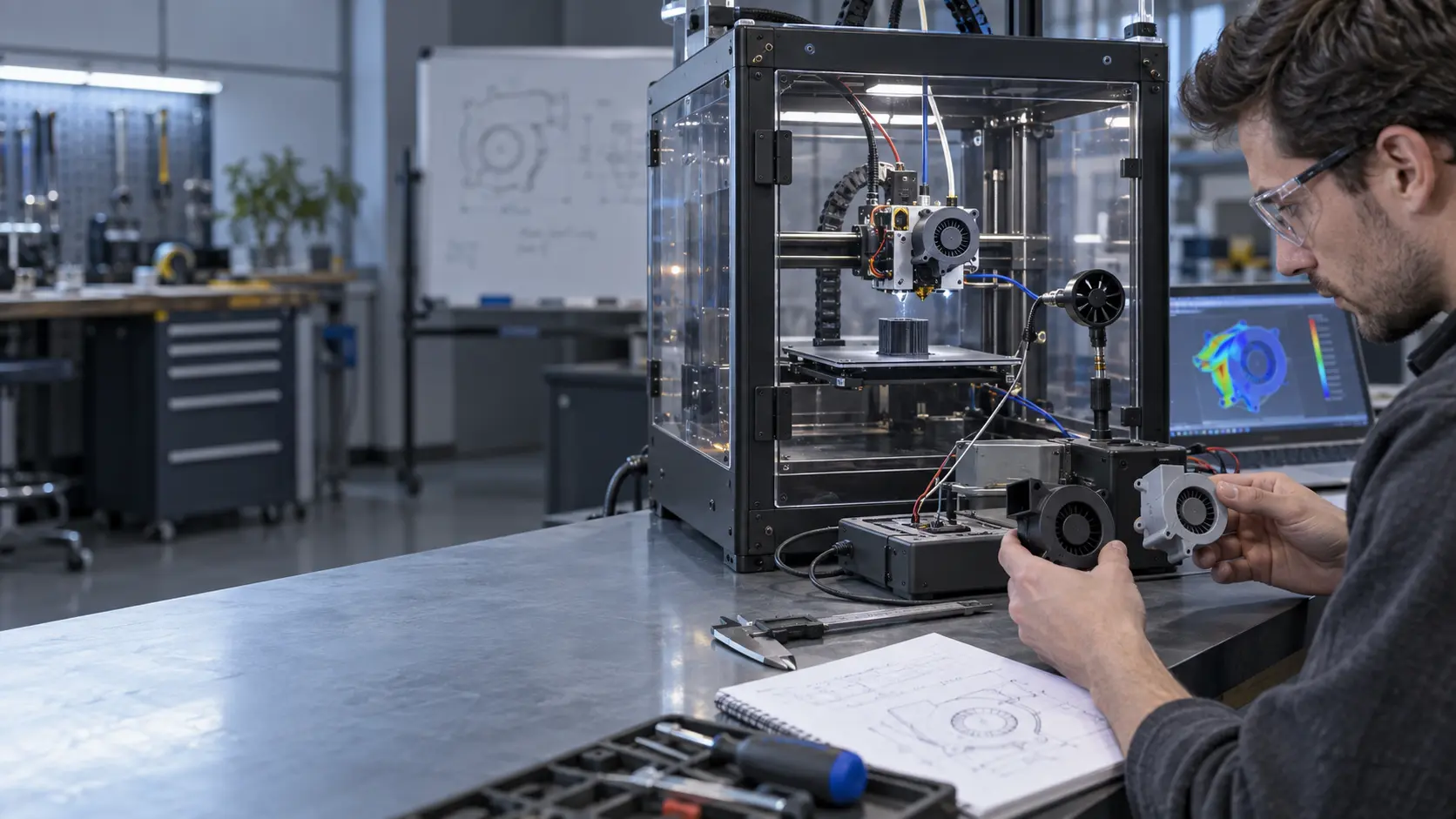
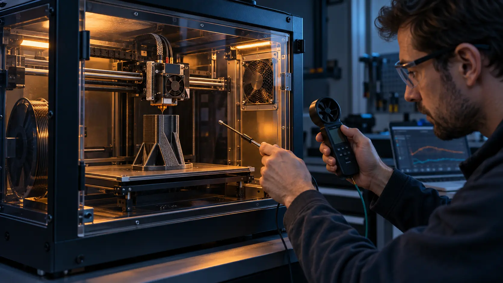
MEGA Tech received the hotend shroud, part-cooling duct, chamber openings, filter path, electronics bay and the customer's fan envelope. A smoke or particle visualization showed that part of the chamber exhaust was being pulled across the hotend intake during one door position. The hotend fan was turning, but its inlet temperature changed with the chamber state.
The team also checked whether the part-cooling duct delivered flow across the nozzle or leaked around the shroud. A high free-air CFM number was not helpful if the duct outlet had a small turning radius and a narrow nozzle slot. The chamber fan was reviewed against the pressure loss of the filter, grille and enclosure opening.
A simple heat estimate was used to size the first test. If 90 W of electronics and motor loss must be removed with a 10 K average air rise, Q = 90/(1,200 x 10) = 0.0075 m³/s, or about 15.9 CFM. This is a screening estimate, not a printer result; the actual design still needs local hotspot measurements and the real pressure path.

Sample 02: Tune Hotend Protection Before Chasing Part-Cooling Flow
The hotend loop was given a stable minimum speed and a clear high-temperature override before the part fan was optimized.
The customer tested startup, low command, sustained hot chamber and print-end cooldown. The fan had to start reliably at the available voltage, maintain useful flow through the heat-break shroud and avoid a resonant tonal peak near the printer enclosure. FG feedback was preferred where the controller needed to distinguish a commanded speed from a real rotor speed.
The acceptance data included heat-break or sink temperature, chamber temperature, nozzle state, fan PWM, RPM or FG, current and the time to recover after a chamber-temperature step. The objective was not maximum air; it was enough heat-break margin without forcing a cold chamber or adding unnecessary noise.
Once the hotend loop was stable, the team adjusted the part-cooling duct and fan. The part fan was evaluated on bridge and overhang test geometry, but also on its effect on chamber temperature. The customer could then change material profiles without accidentally changing the protective hotend duty.
| Loop | Primary job | Evidence |
|---|---|---|
| Hotend protection | Prevent heat creep and protect the heat break | Heat-break temperature, startup, FG and low-voltage behavior |
| Part cooling | Control solidification, bridges and overhangs | Duct flow, print geometry and chamber disturbance |
| Chamber circulation/exhaust | Manage enclosure temperature and moisture/odor path | Layer temperature, exhaust pressure and filter loading |
Sample 03: Build a Material-Aware Chamber Control Curve
The revised sample used different fan limits for cool materials and heated-chamber materials instead of one global maximum.
For PLA, the chamber loop could use a higher exhaust command when the chamber approached the material limit, while the part fan could respond to bridge demand. For ABS or ASA, the chamber exhaust remained limited during the build and the circulation fan mixed the enclosure without creating a cold jet at the print surface. The exact temperatures remained product-specific and were defined by the customer process team.
The customer also measured the filter path. A filter can reduce noise and help manage particles, but it adds pressure loss. If a chamber fan consumes 4 W for a 6-hour print, it uses about 24 Wh before controller losses. If a replacement fan consumes 2.5 W at the same installed duty, the screening saving is 9 Wh per print. These are illustrative calculations, not customer data; the decision still depends on installed flow and print quality.
The fan sample was adjusted around frame depth, connector, cable exit, PWM response and the real filter and grille. A nominally compatible replacement was not accepted until it reproduced the required installed behavior.
Validation: Heat Creep, Warping, Noise and Recovery
The printer team repeated the same tests across material modes and after the enclosure had reached thermal steady state.
The test matrix included a long PLA print, a heated-chamber engineering-material print, bridge geometry, a door-open disturbance, a filter-loaded condition and a post-print cooldown. Thermocouples or temperature sensors were placed at the hotend intake, heat sink, chamber top and chamber center. The fan log included PWM, RPM or FG, current and fault behavior.
The customer checked not only whether a print finished, but when the failure symptoms appeared. Heat creep can develop after hours of operation even when a short test looks normal. A chamber fan can also appear successful until the filter loads or the machine is placed near a wall. The pressure and temperature state at the actual installation had to be retained with the sample.
Acoustic review covered steady speed, ramping, part-fan tonal peaks and enclosure-panel vibration. The target was a stable, predictable sound signature rather than a misleading single dB number. The final design review documented which changes would require retesting: fan frame, duct, filter, material profile, chamber temperature, firmware limit or mounting.
Result: A Production-Ready Sample With Clearer Thermal Trade-Offs
The customer received a fan and control configuration that could be evaluated against print modes instead of a compromise setting that was acceptable nowhere.
The revised sample protected the hotend independently, delivered part cooling through the actual duct and allowed the chamber loop to follow the material state. The operator could now increase chamber stability for high-temperature materials without automatically overcooling every layer, while PLA mode could protect against heat creep without running the entire enclosure at maximum exhaust.
The case also gave procurement a more useful specification. The fan was described by installed pressure, flow direction, low-speed behavior, voltage range, PWM/FG interface, connector, acoustic target and sample validation, not only by frame size or free-air CFM.
MEGA Tech supported the project from the customer's physical sample through fan selection, duct and control adjustment and installed validation. The printer manufacturer retained responsibility for the complete motion system, heater safety, material process window and final product certification.
How MEGA Tech Supports 3D-Printer Fan Development
We help printer teams turn a hotend, duct and chamber constraint into a testable fan sample.
MEGA Tech can review compact DC axial fans and centrifugal blowers for hotend heat-break cooling, part-cooling ducts, chamber circulation, electronics bays and filter-assisted exhaust. The review can cover frame and thickness, pressure-flow behavior, PWM, FG/RD, connector, cable exit, bearing option, temperature range, noise, vibration and small-batch samples.
For a first review, send the printer sample or 3D section, hotend and chamber temperature states, material modes, duct and filter path, fan envelope, voltage tolerance, control interface, acoustic target, print duty and quantity. We can help compare a replacement fan with a customized sample and then test it on the actual printer.
We do not claim that a fan alone guarantees print quality. The nozzle, heat break, heater, firmware, material, enclosure and motion system remain part of the printer manufacturer's validation.
Engineer Questions About This 3D-Printer Case
Use these questions before freezing a fan, shroud or chamber-control profile.
Q: Can one fan serve the hotend and chamber? A: It can create unwanted interactions. Separate the thermal jobs first and only combine them after the air paths are measured.
Q: Why can a printer print for hours and then develop heat creep? A: Chamber temperature, heat soak, filter loading and low hotend airflow can change after the system reaches steady state.
Q: Does a higher part-fan CFM always improve bridges? A: No. Duct pressure, outlet direction, material, layer time and chamber temperature determine the useful result.
Q: What does MEGA Tech need for a sample? A: Printer sample, three air paths, material modes, temperature targets, pressure restrictions, voltage, control interface, noise target and quantity.
Q: Should the fan be selected by frame size? A: Frame size is only a mechanical constraint. Installed P-Q behavior, control, noise and startup must be verified.
3D-Printer Cooling Design Review Checklist
A compact checklist for thermal, mechanical, firmware and purchasing teams.
- Are hotend, part-cooling and chamber air paths separated and named?
- What temperature does each loop protect or control?
- Has the printer reached thermal steady state before acceptance?
- What pressure do shroud, duct, filter and grille add at target flow?
- Is the fan stable at minimum PWM and reliable at startup voltage?
- Does FG/RD feedback reflect the real rotor state?
- How do PLA, ABS, ASA and nylon modes change fan limits?
- Has the chamber fan been checked for wall vibration and tonal noise?
- Which changes require a new sample test: shroud, duct, filter, firmware or fan?