
What kills fans inside welders
Two field stories: the fan buried in grinding dust, and the impeller cratered by a single spatter ball.
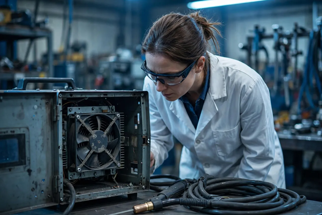
A fabrication shop runs three shifts. Six months in, the MIG welders start tripping on thermal overload — not during welding, but between welds, when the cooling fan should be catching up. The teardown finds the fan buried in grinding dust and metal fines, its impeller caked until it barely moves air. The fan was rated for industrial use. The shop air was not industrial air.
The other killer is faster and more dramatic. A spatter ball — a molten droplet flung from the arc — lands on a standard plastic impeller, melts a crater into a blade, and throws the rotor out of balance. The fan vibrates itself to death in a week. The failure report says “mechanical damage.” The root cause is material selection.
Welders are among the harshest homes a cooling fan can have: conductive metal dust that shorts electronics, hot spatter that attacks plastics, ambient temperatures that start high and climb, and duty cycles that run the fan harder than most designers assume. This article explains the four stressors, how to select and protect fans for welding equipment, the four misconceptions that ship bad fans, and five buyer checkpoints.
The four stressors of welding equipment
Conductive dust, hot spatter, high ambient plus duty cycle, and arc EMI — interacting, never isolated.
Conductive metal dust: grinding, cutting and the welding process itself fill the air with fine metal particles. Unlike ordinary dust, this dust conducts electricity — when it settles on a driver board, it creates leakage paths and short circuits. It also packs into bearings and heat-sink fins with a persistence that ordinary dust never achieves.
Weld spatter and hot particles: molten droplets travel surprising distances from the arc. Plastics that survive 100 °C continuous service can still be cratered by a single 1,000 °C droplet. Impellers, guards and housings near the work zone need materials chosen for spatter resistance, not just temperature rating. High ambient temperature plus duty cycle: a welder’s rated duty cycle — say 60% at 40 °C ambient — describes the welding output, but the fan lives inside the same enclosure, cooling power electronics that stay hot between welds. Design the fan for the enclosure’s reality: elevated ambient, limited airflow paths, and heat that does not clock out when the arc stops.
Electromagnetic interference: the arc is a broadband noise source, and the welder’s own switching electronics add conducted and radiated EMI. The fan’s driver must neither malfunction in this environment nor add to it — EMC behavior belongs in the validation plan. These four interact: dust plus humidity corrodes, heat plus dust bakes deposits into insulation, vibration plus spatter-damaged blades accelerates imbalance. Test them in combination, not isolation.
Dust: the metal kind changes everything
Filtration becomes electrical protection — and a clogged filter just schedules the failure for later.
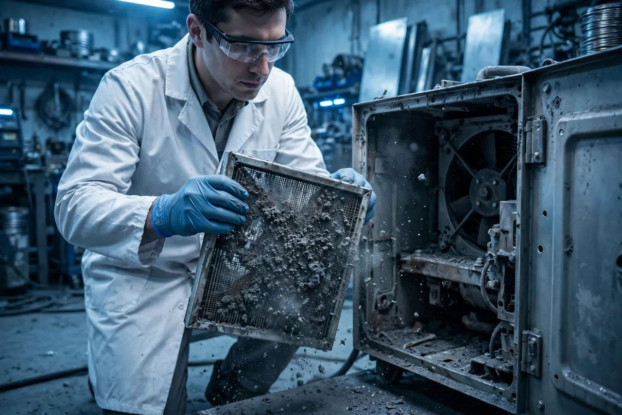
Ordinary dust selection logic — filters, IP ratings, maintenance intervals — needs an upgrade when the dust conducts. Filtration becomes electrical protection, not just airflow protection: a filter that keeps the fan breathing also keeps conductive particles off the driver electronics. But filters clog, and a clogged filter starves the fan — which is why filter maintenance intervals must be defined, documented, and realistic for a three-shift shop, not a clean lab.
IP ratings need re-reading: an IP5X dust-protected fan keeps most dust out of the motor, but the driver board and connectors may live outside the sealed zone. Map the IP rating to the actual dust-sensitive parts, not just the motor. Bearing and motor protection: sealed bearings resist dust ingress far better than shielded ones, and the cost difference is trivial against a field failure. For the motor itself, consider whether the winding insulation class and any conformal coating match a conductive-dust environment — dust plus condensed humidity is the combination that kills boards.
The practical rule: assume the dust gets everywhere the air goes, because it does. Protect the electronics as a system — filtration, sealing, coating — rather than hoping the fan’s IP rating covers parts it was never tested with. One more design consideration that buyers often miss: filter clogging margin. A clean filter has a known pressure drop; a loaded filter can double or triple it, and the fan rides up its P-Q curve to a lower airflow point as the filter loads. Size the fan so that it still meets the thermal requirement with a partially loaded filter — not just a clean one — or the first month of dust quietly derates your cooling. If the application cannot tolerate that margin, a differential-pressure indicator across the filter turns “when someone remembers” into a signal the shop can act on.
Spatter, heat, and material selection
Heat resistance and spatter resistance are different properties — test with representative spatter, not just the temperature datasheet.
Spatter resistance is a materials question with a short answer: metals and high-temperature engineering plastics where droplets can land, standard plastics only where they cannot. Impeller materials: glass-filled nylon and similar engineering plastics handle continuous heat well but can still be notched by molten droplets — in direct spatter zones, metal impellers or spatter shields earn their keep. The choice depends on distance from the arc and whether a guard can intercept the droplets first.
Guards as sacrificial parts: a well-designed guard keeps fingers out (safety) and takes the spatter hits (sacrificial). Design guards to be replaceable and inspectable — a guard pitted by spatter is doing its job, and replacing it beats replacing the fan. Housing and mounting: the fan housing near hot zones should resist both radiant heat and droplet impact, and mounting hardware needs the same consideration — a melted mounting grommet lets the fan shift, which changes the airflow path and starts a vibration problem.
Thermal validation with spatter in mind: standard thermal testing proves the fan moves enough air. Spatter-aware validation adds the damage question — after representative spatter exposure, does the impeller still balance, do the guards still guard, does the fan still meet its airflow? This is a separate test from the thermal test — schedule both.

Duty cycle: the number everyone underestimates
The welder’s duty cycle is not the fan’s duty cycle — size for the enclosure’s reality.
Welder duty cycle ratings describe arc-on time — but the fan’s duty is different. Between welds, the power electronics are still hot and still need cooling; in many shops the fan runs effectively continuously across a shift. Size for continuous duty: if the fan only just meets the thermal requirement at the welder’s rated duty cycle, it will run at its limit all day in real service. Size with margin for continuous operation at the enclosure’s actual ambient.
Thermal cycling of the fan itself: welders cycle between arc-on heat and idle cooling, and the fan rides those cycles — solder joints, bearing grease, and housing materials all age with cycling. Control strategy: temperature-controlled fan speed — running hard when the enclosure is hot, easing off when it cools — reduces dust ingestion (less air moved means less dust pulled in) and extends bearing life. But the control must be validated against the real thermal profile, including the between-welds heat soak that catches undersized designs. Ask the welder manufacturer for the enclosure’s thermal profile, not just the welder’s duty cycle rating. The fan cools the enclosure; size it for the enclosure.

Four misconceptions that ship bad fans
The four beliefs that survive every design review — and keep causing field failures.
Misconception 1: “IP54 is enough for a welder.” IP54 keeps most dust out of the tested enclosure — but conductive dust on unsealed electronics outside the motor, clogged filters starving airflow, and spatter damage are all outside what the IP test measures. IP rating is one input, not the selection.
Misconception 2: “A filter solves the dust problem.” A filter trades one failure mode for another: dust ingress becomes filter clogging. Without a defined and followed maintenance interval, the filter just schedules the failure for later. In shops where maintenance is aspirational, consider filterless strategies — sealed electronics, oversized heat paths — alongside filtration.
Misconception 3: “High-temperature plastics are spatter-proof.” Heat resistance and spatter resistance are different properties. A plastic rated for 150 °C continuous service can still be cratered by a molten droplet at 1,000 °C+. Test with representative spatter, not just the temperature datasheet.
Misconception 4: “The fan only works as hard as the duty cycle.” The welder’s duty cycle is not the fan’s duty cycle. Between-welds heat soak, three-shift operation, and hot enclosures mean the fan often works harder and longer than the rating suggests. Size for the enclosure’s reality.
Five buyer checkpoints for welder fans
Five questions that turn “industrial grade” from a slogan into a specification.
Checkpoint 1: characterize the dust. What particles, what size, conductive or not, what concentration? “Metal dust” is not a specification — get the particle story from the application before selecting protection. Checkpoint 2: map the spatter exposure. Distance from the arc, droplet sizes, which fan parts are in the line of fire. This map drives impeller material, guard design, and housing choices.
Checkpoint 3: define the real thermal duty. Enclosure ambient profile across a shift, between-welds heat soak, worst-case summer conditions. Size the fan for continuous operation at that reality, with margin. Checkpoint 4: specify filtration and its maintenance. Filter type, clogging indicator or interval, who changes it and how often — in writing. If maintenance cannot be guaranteed, design the protection to survive without it.
Checkpoint 5: validate in combination. Dust plus heat, spatter plus vibration, thermal cycling plus humidity — the combined tests, not just the single-stress clauses. The field never applies one stress at a time.
The design details that decide survival
Sealed bearings are not an upgrade here — they are the baseline.
Sealed bearings as standard: in conductive-dust environments, sealed bearings are not an upgrade — they are the baseline, and the cost delta is noise against a single field failure. Driver electronics protection: conformal coating, sealed enclosures for the control board, connectors rated for the environment — remember the failure mode, conductive dust plus humidity equals leakage currents and shorts, so design the board like it will get dusty, because it will.
Impeller and guard materials per the spatter map: engineering plastics where droplets cannot reach, metal or shielded designs where they can, sacrificial guards that are cheap to replace — revisit the map whenever the welder layout changes. EMC hardening: filtered power input, sensible grounding, driver firmware that rides through arc noise without misbehaving — validate against the welder’s actual EMI environment, not a generic industrial profile.
Serviceability: filters, guards, and fans that can be inspected and replaced without disassembling the welder. A fan that takes an hour to reach will not get its filter changed — and then Checkpoint 4 fails in the field.
How MEGA Tech supports welding equipment projects
Design for the shop floor, not the catalog.
Welding equipment rewards suppliers who design for the shop floor, not the catalog. MEGA Tech supports welder thermal projects through its standard five-step engagement: custom cooling fan development and manufacturing, fan selection, airflow path review, sample validation, and mass production.
In practice: selection starts from the dust characterization and spatter map (Checkpoints 1–2), so protection is designed rather than hoped for; airflow path reviews account for filter pressure drop and clogging margin; sample validation runs the combined dust-heat-spatter tests the field will apply; and mass production holds the validated configuration steady with change control.
Engineer FAQ
Short answers to the questions buyers actually ask.
Q: Can we just use a higher-IP fan instead of dealing with filters? A: A higher IP rating protects the motor better, but it does not protect unsealed electronics, does not stop filter-equivalent airflow starvation (a sealed fan still needs to breathe), and says nothing about spatter. IP rating is part of the answer, not the answer.
Q: How often do filters really need changing in a welding shop? A: It depends on dust loading, which varies enormously between shops — which is why the interval must be validated against the actual environment, with a clogging indicator or a conservative schedule. “When someone remembers” is not an interval.
Q: Are metal impellers always better for welders? A: Not always — they cost more, weigh more, and can be noisier. Use them (or spatter shields) where the spatter map says droplets reach; use engineering plastics where they do not. The map decides, not a blanket rule.
Q: Does the fan need to be rated for the welder’s full duty cycle? A: The fan needs to be rated for its own real duty — which is usually harder than the welder’s arc-on duty cycle because of between-welds heat soak and continuous shop operation. Size for the enclosure’s thermal reality.
Q: What is the most commonly missed failure mode? A: Conductive dust plus humidity on the driver board — it does not show up in clean-lab validation, it develops slowly, and it looks like random electronic failure in the field. Conformal coating and sealed electronics are cheap insurance.
Q: Should fan speed be temperature-controlled in a welder? A: Usually yes — it reduces dust ingestion during light thermal loads and extends bearing life. But validate the control against the real thermal profile including heat soak, and make sure the control electronics themselves survive the EMI environment.
Questions for your next design review
Bring these to the review; leave with a specification you can defend.
- What is the dust characterization — particle type, size, conductivity, concentration?
- Do we have a spatter exposure map for every fan part?
- Is the fan sized for continuous operation at the enclosure’s real ambient — with margin?
- What is the filter maintenance interval, and who owns it?
- Are the driver electronics protected against conductive dust plus humidity?
- Were combined dust-heat-spatter tests run — or only single-stress clauses?
- Can the fan, filter and guards be serviced without major disassembly?
- Does the validation cover the between-welds heat soak, not just arc-on conditions?
