
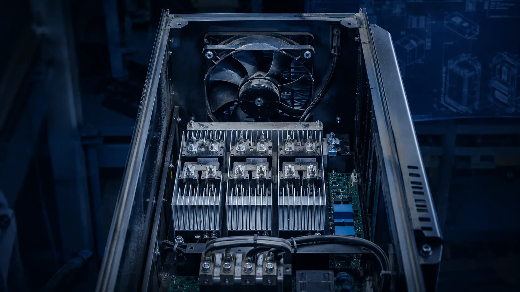
Start with drive and UPS losses
A cabinet fan is selected from the heat that remains inside the enclosure, the allowable temperature rise and the pressure path.
VFDs, UPS modules, rectifiers, contactors, PLCs and power supplies do not turn all input power into useful output. Start by identifying the losses that become cabinet heat in the operating state that matters. Use manufacturer loss data where available, add auxiliary electronics and state whether the value is continuous, overload or short duration. Do not use the motor rating as a substitute for the drive's actual loss.
For a first estimate, use Q = W / (rho x cp x delta-T). As an illustration, 900 W of cabinet heat at 1.20 kg/m3, 1,005 J/(kg K) and an allowed 12 K air rise requires about 0.062 m3/s, or 131 CFM. That is only a heat balance. The fan must still produce the required airflow after the filter, grille, heat sink, cable path and outlet losses are included.
Write the temperature basis beside the calculation. A drive cabinet in a 45 °C plant area has less margin than the same cabinet in a 25 °C laboratory. If the component limit is specified at the hottest semiconductor case, do not validate only the average cabinet air temperature. Identify the sensor locations and the component that sets the limit before selecting the fan.
Separate continuous heat from short overload heat. A UPS may have a brief transfer or recharge event, while a VFD may operate at a sustained high-load speed for hours. The fan control can use different commands for these states, but the thermal model must show which state controls the component temperature and which state controls the response time. If a transient is short enough to use thermal capacitance, document that assumption and verify it with a time trace rather than silently reducing the fan requirement.
Turn filters and grilles into a pressure budget
A high free-air CFM number can fail in a control cabinet when the system pressure is not included.
List the inlet grille, filter, finger guard, heat sink, drive passage, wiring obstruction, bend and outlet louver. Obtain each loss at the target airflow, not at an unrelated catalogue flow. A filter pressure value should include the clean state and the loaded state used for maintenance or alarm planning. If the enclosure uses positive pressure, include leakage and outlet restriction in the same system definition.
Pressure loss is flow-dependent. Filter face velocity, free area and the distribution across a heat sink can matter as much as nominal fan diameter. Keep pressure units consistent and record whether a number is static pressure, total pressure or a differential measured across a component.
The operating point is where the fan curve meets the cabinet system curve. The zero-pressure airflow printed on a product card is not the cabinet airflow, and maximum pressure at zero flow is not a useful cooling result by itself. Compare candidate fans at the pressure the cabinet needs, then confirm the result in the enclosure.

| Restriction | Required input | State | Proof |
|---|---|---|---|
| Inlet grille | Pressure at target airflow | Clean and blocked | Differential-pressure reading |
| Filter | Clean and loaded curve | Maintenance limit | Filter test or supplier data |
| Heat sink and drive path | Pressure through assembly | Worst component path | Cabinet pressure taps |
| Outlet louver | Loss at exhaust flow | Louver position | Exhaust-side measurement |
| Total system | Sum at target airflow | Normal and fault state | Fan/system curve check |
Do not confuse fan speed with cabinet cooling
A fan can report normal RPM while the enclosure is recirculating hot air or losing airflow through a bypass path.
Check the direction of the air path first. A short circuit from inlet to outlet can make the fan look successful while the drive heat sink remains in a warm recirculation pocket. Cable entries, removable panels and unsealed filter frames can also create a low-resistance path that steals flow from the component that needs it.
Measure temperature at the drive heat sink, DC-link area, UPS power module and air leaving the critical path. Compare those temperatures with inlet air and with fan pressure and airflow readings. A single outlet temperature or cabinet average can hide a local hotspot behind a busbar or dense wiring channel.
If the fan has FG or RD output, use it as a diagnostic signal rather than proof of airflow. Combine speed or alarm information with temperature and, where practical, filter differential pressure. A stopped fan, slipping connector and blocked filter can produce different signals and need different responses.
Look for thermal stratification when the cabinet is tall or the heat sources are unevenly placed. Hot air can collect near the top while the fan sensor remains in a cooler return stream. A small number of sensors placed only near the inlet can therefore report a healthy cabinet while a high-mounted capacitor, rectifier or UPS module is operating at a higher temperature. Measure several heights during the prototype test and keep the worst location in the acceptance record.
Airflow visualisation is useful as a diagnostic, but it is not a substitute for a pressure or temperature measurement. Smoke, tufts or a simple particle visual can show recirculation and bypass. Once a problem is found, confirm it with a pressure tap, an airflow traverse or a temperature comparison. The purpose is to change the air path or the fan duty based on evidence, not to make the cabinet look full of moving air.
Screen the electrical interface before choosing a fan
Voltage, current, control, connector and restart behaviour are part of the cabinet cooling function.
Record the voltage at the fan connector during startup, steady operation and the worst converter condition. A nominal 24 V or 48 V label does not define the exact allowable range for every variant. Include wiring drop, protection devices, connector contact resistance and current during starting or locked-rotor protection.
For PWM, document command voltage, frequency, minimum duty, start duty and restart behaviour. For FG or RD, define pulses per revolution, pull-up arrangement, alarm polarity and controller threshold. Test the interface with the actual VFD or UPS controller rather than a laboratory signal generator alone.
AC, DC and EC options should be compared from the full system boundary. The correct choice depends on the available rail, speed control, pressure requirement, noise limit, space and environment. Do not treat a product family label as evidence of a certification or environmental rating absent from the exact product record.
If a controller reduces speed at light load, verify the minimum stable speed and the restart command. Some cabinet problems appear only after a low-speed period followed by a sudden drive or UPS load step. Record the time from command change to airflow recovery and the temperature response of the critical component. This makes the control decision measurable instead of relying on a visual impression that the fan is turning.
The connector and harness should be reviewed with the same care as the fan. A contact that is acceptable at a low current can create a meaningful drop when several fans start together. Record the connector part number, mating condition, cable length, protection device and measured voltage at the fan. If a service technician can unplug one fan while the cabinet is live, define the restart and alarm behaviour for that action rather than leaving it to trial and error.
Check temperature, altitude and dust as one design case
Industrial cabinets often combine high ambient temperature, dust loading, vibration and restricted service access.
State minimum and maximum ambient temperature, altitude, humidity, vibration, dust exposure, filter service interval and mounting orientation. Air density affects both the heat-balance calculation and aerodynamic result. Dust changes filter pressure and maintenance interval. Vibration and shock affect mounting and the connector, not only the motor.
A high-temperature test should include the same filter and airflow path as the final cabinet. Running a fan in open air at room temperature does not prove the drive will remain within its limit inside a warm panel. If the fan is speed-controlled, test the control curve at the thermal conditions where the controller will operate.
MEGA can review the fan's required airflow, pressure, voltage, control and sample validation. Finished enclosure sealing, safety design, fire function and control-cabinet compliance remain with the equipment owner and system integrator.
Noise also has to be measured in the installed cabinet. A fan's published sound value can be taken under a particular test method and distance, while a VFD cabinet adds grille turbulence, panel vibration and tonal components from the drive. Record the microphone position, fan command, pressure, airflow and cabinet panels used. If the cabinet is installed near an operator station, compare the complete assembly rather than promising that a lower catalogue dBA number will produce a quieter machine.
Service access is a thermal requirement as well. A filter that cannot be removed without disturbing the power electronics will be left in service longer, increasing pressure loss and reducing airflow. Design the maintenance state into the acceptance plan: identify the filter replacement limit, the alarm threshold, the safe fan restart sequence and the evidence that the cabinet returns to its intended operating point after service.
Validate clean, loaded and restart states
The cabinet should be tested in states that can create a thermal trip, not only in a comfortable nominal run.
Record fan-side voltage, current, command, speed or tach, airflow, static pressure, filter differential pressure and critical component temperature. Repeat the test with a clean filter and the specified loaded-filter state. Include low-speed operation, full-load operation, restart after power interruption and the planned alarm response.
The acceptance table should name the measurement location and stabilization time. If a pressure tap is upstream of the filter in one test and downstream in another, the numbers are not directly comparable. If a thermocouple moves between tests, note the location and uncertainty. Good records make a sample decision faster because the gap is visible.
When replacing a reference fan, test both candidates with the same fixture, pressure path, voltage, command, ambient and acceptance limit. Same outline dimensions and similar free-air CFM do not establish equivalence. Check the mounting seal, connector, control response and loaded operating point before approval.
A useful sample report records what was not tested. If the filter was clean only, say so. If the test used a room-temperature bench supply rather than the cabinet converter, say so. If the temperature sensor was outside the hottest drive row, show the limitation. Transparent gaps make the next sample more efficient because the team can decide whether it needs a different fan, a different air path or simply a better measurement.
For a UPS, include the transition state that occurs when the supply changes or the battery path takes over. For a VFD, include the motor duty and switching condition that create the highest sustained loss. The fan may be required to accelerate, hold a command or report an alarm during the same event. A nominal steady-state test cannot answer those transient questions, so put them explicitly in the validation matrix.
Recommended catalogue starting points
These product pages are candidate starting points for a VFD or UPS cabinet review, not automatic substitutions.
The correct series depends on heat load, installed pressure, voltage, control, noise, space and environment. Request a sample recommendation with the cabinet duty rather than selecting from frame size alone.
Engineer FAQ: VFD and UPS cabinet fans
A practical selection starts from the cabinet heat source and pressure path, then proves the result in the final enclosure.
Q: Can I size the fan from the VFD motor rating? A: No. Use the drive or UPS loss that becomes cabinet heat, then calculate a first airflow and add system pressure.
Q: Is a high free-air CFM fan automatically better? A: No. Compare airflow at installed pressure and verify it with the filter, grille and cabinet path in place.
Q: Does normal RPM prove the cabinet is cooled? A: No. Measure airflow, pressure and critical-component temperature, and check bypass or recirculation.
Q: Can MEGA supply a complete VFD or UPS cabinet? A: No. MEGA develops and manufactures custom cooling fans and supports fan selection, air-path review and sample validation. The cabinet, controller and safety design remain with the integrator.
Q: What should I send for a sample recommendation? A: Send heat load, airflow and static pressure, temperature and altitude, voltage, PWM or FG/RD, connector, space, noise target, environment and quantity.
Questions for a design review
Use these questions before releasing a VFD or UPS cabinet cooling design.
- Which drive, UPS or power-electronics losses become cabinet heat at the worst duty?
- What air density and allowable temperature rise were used in the airflow estimate?
- Which filter, grille, heat sink, cable path and outlet losses make up the pressure budget?
- What is the clean-filter and loaded-filter acceptance state?
- Where are pressure taps and component temperature sensors located?
- Is the PWM, FG or RD interface compatible with the actual controller?
- What happens after power interruption, locked rotor or a filter alarm?
- Has the replacement been compared at the same installed operating point?
From cabinet duty point to a validated custom fan sample
MEGA Tech develops and manufactures custom cooling fans — from fan selection, air-path review and sample validation to volume production. For VFD and UPS cabinets, we can review frame and thickness, airflow, static pressure, voltage, PWM, FG or RD output, connector, noise target and environmental constraints, then define a sample test in the customer's enclosure.
Send the heat load, required airflow and static pressure at that airflow, temperature and altitude basis, supply range, control interface, connector, available envelope, noise measurement point, environment, quantity and filter acceptance state. We will separate catalogue starting points from values that must be measured in the assembly.
Our scope is the custom cooling fan and its validation in the customer's equipment. We do not supply the VFD, UPS, cabinet, coil, liquid loop, unit controller, cabinet safety design or emergency ventilation function. For a sample discussion, email inquiry@cnmegatech.com or use WhatsApp at +86 135 7056 7086.
