

A VFD cabinet is cooled by airflow that knows where to go, not by how big the fan is
A variable-frequency drive can be efficient and still put a significant heat load into the enclosure. The correct loss must come from the drive's efficiency curve at the real load and switching condition, and the impact on component life must come from the component and drive thermal data. The cabinet cooling fan is doing far more than keeping things comfortable.
Do the heat-load arithmetic before anyone picks hardware. Start with the drive manufacturer's loss data at the actual load, then add power supplies, contactors, braking components, control electronics and environmental gains. For illustration only, a 30 kW drive at 80% load with an assumed 4% loss contributes about 960 W; the real value must be confirmed from the selected drive. Outdoors, add solar gain from cabinet area, finish, orientation and site irradiance rather than a fixed wall-wattage assumption.
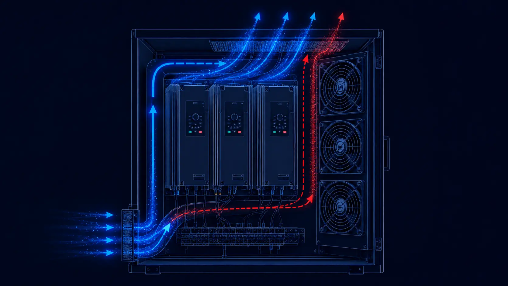
Yet the most common reason a tooling cell trips on over-temperature is not a weak fan. It is air that never reaches the heat sinks at all — it slips through the gaps beside a VFD, or it short-circuits straight from the inlet to the outlet and leaves the components downstream untouched. A fan can be moving plenty of air and still be cooling almost nothing useful.
This article is about the difference between a cabinet that moves air and a cabinet that directs it: the bypass and short-circuiting pitfalls, the airflow rules the drivetrain guides use, the static-pressure floor a filtered cabinet demands, and the trade-off between sealing the cabinet (IP protection) and letting heat escape.
Bypass and short-circuiting — the two ways air misses its job
Inside a control cabinet, cooling air follows paths, not wishes. Two common defects waste it. The first is heat-sink bypass: the air approaches a finned heat sink and a large share of it streams around the sink's sides and top instead of through the fins, because that clearance zone is the path of least resistance. The air that actually enters the fin passages — the only air doing any cooling — can be far less than the fan is moving.
The effect can become more severe as fin resistance rises, and it is a classic gotcha in sealed cabinets where components are packed tight against shroud edges. Widening the clearance around the sink does not automatically help — without a shroud or seal, it can make the bypass easier.
The second defect is cabinet short-circuiting: warm inlet air cuts straight from inlet to outlet through the least-resistance lane and recirculates, so the components behind it suffocate in still air. Both failures share one cause — the airflow was never directed, only supplied.
Tall cabinets add a third, quieter defect: stratification. The top-to-bottom gradient depends on cabinet height, heat sources, cable ducts and airflow rate, so it should be mapped with sensors or CFD rather than assumed. Countermeasures include a clear vertical path, sensible placement of high-loss components, baffles and a small internal circulation fan sized from the measured temperature map.
And one heat source is routinely forgotten in the balance: busbar joints. As an engineering example, 2,500 A through an extra 10 µΩ contact resistance dissipates about 62.5 W in a small joint. The actual current, resistance and duty cycle must be measured or specified for the assembly. Commissioning thermography finds these concentrated hot spots, not airflow calculations.
The airflow rules drivetrain engineers actually use
The fundamentals are stable across manufacturers, but the values are not. The cabinet fan must be sized from the cabinet heat balance and the drive manufacturer's required airflow or pressure, then checked against enclosure resistance. The inlet should be low-resistance, and in dusty environments it must carry a filter selected for acceptable pressure drop and a defined cleaning schedule.
The standing layout rule for forced ventilation is: air must not short-circuit from inlet to outlet, and hot air must not recirculate. That is exactly what internal baffles are for. Positive-pressure or negative-pressure arrangements can both be valid; the choice must match the filter, enclosure, leakage path and IP target. Inlet and outlet placement should be selected from the cabinet airflow map, often using low-to-high and opposed paths, but the final geometry belongs to the specific cabinet.
Clearance around drives is also model-specific. Follow the drive manual for vertical, side and above/below spacing, and use baffles when units are stacked so one drive does not breathe another's exhaust. Do not remove vent covers or change the cooling path without confirming the drive manufacturer's installation and safety requirements.
- Size cabinet fans from drive loss, allowed temperature rise and the loaded system curve, with smooth, gradual direction changes in the flow path.
- Choose positive or negative pressure only after checking the filter, leakage path, service environment and IP target; place inlet and outlet to sweep the measured hot zones.
- Keep the inlet low-resistance; add a low-drop filter in dusty sites and schedule it for cleaning.
- Use the selected drive manual's clearance requirements and baffle any vertical stacking.
- Do not remove drive vent covers or change the internal airflow path without manufacturer approval and thermal validation.
The fan has to push through a filter — static pressure decides whether it can
Every filter, duct and packed module adds resistance, and the fan's airflow at that resistance — not its free-air figure — is what reaches the drives. Filter pressure drop depends on media, face velocity, dust loading and moisture, so a fixed percentage is not a safe design input. A standard axial fan tuned for free air can collapse against a loaded dust filter, which is exactly the scenario that trips a production cell: the filter is clean enough to look fine, but its pressure drop has already starved the airflow.
The sizing arithmetic is simple enough to do on a whiteboard. A first-order air-cooling estimate is airflow (m³/h) ≈ heat load / (air heat-capacity factor × ΔT), with the factor set by the selected units and site conditions. For illustration, 800 W with a 13 K allowed rise is about 180–200 m³/h before altitude, recirculation and filter margin; select a fan that holds the required flow at the complete loaded system resistance.
This is why specifying a high-static-pressure fan matters in cabinets with filters and dense contents, and why the inlet filter is chosen for low pressure drop in the first place. The drive guides put it directly: fan and filter selections routinely compromise an enclosure's thermal performance — and, too often, its IP rating.
Choose the fan at the loaded-filter working point so that even as the filter ages, it still holds enough airflow across the heat sinks — the budget you build in against dust is headroom you keep on site.
| Model | Size / 24V | Free-air CFM | Static pressure | Noise |
|---|---|---|---|---|
| MG12038HV24X | 120×120×38 mm | ~210 CFM | ~29 mmH2O | ~65 dBA |
| MG8038HV24X | 80×80×38 mm | ~129 CFM | ~127 mmH2O | ~79 dBA |
| MG8025HV24X | 80×80×25 mm | ~61 CFM | ~9 mmH2O | ~46 dBA |
Know the cooling ladder — a filter fan has a hard ceiling
One rung up sits the air-to-air heat exchanger: two isolated fan loops through a heat-transfer core, with internal air kept separate from external air. Its rating is commonly expressed as a thermal conductance or W/K, and the removable heat depends on that rating and the actual interior-to-ambient temperature difference. It cannot cool below ambient, but it can preserve enclosure separation at contaminated sites.
The next rung is a panel air conditioner or another closed-loop solution when the enclosure must stay sealed or the required interior temperature is below ambient. Selection then depends on heat load, ambient range, condensate management, condenser fouling and service access. For severe dust, compressed-air or liquid solutions may be considered where the site can support their maintenance and safety requirements. The selection is a heat-load and environment decision first, not a brand decision.
A worked example shows why the ladder matters. Four 75 kW drives with an illustrative 1.5 kW loss each put about 6 kW into a panel. If the allowed interior-to-ambient rise is only 5 K, a first-order air calculation requires roughly 3,500–3,600 m³/h before system margin and recirculation. A compact filter fan is unlikely to provide that at a sealed-cabinet pressure drop; the honest answers are closed-loop cooling, splitting the drives across sections or externalizing the heat path — decided before the enclosure is frozen.
Sealing the cabinet fights the heat — IP class is a thermal trade-off
Raise the enclosure to a higher IP target and you reduce free air exchange, but you also increase the thermal design burden. The same enclosure can hold more heat and force all heat rejection through a filter, heat exchanger, conditioner or external heat path. IEC 60529 defines the IP classification method; the complete enclosure, fan grille, filter frame, gasket and service condition must be tested as an assembly.
The conflict is at every opening: a filter-fan grille, cable gland or service panel can change the tested ingress performance if it is not part of the certified enclosure design. Do not infer a new IP code from a component label, and do not assume a generic filter fan preserves the cabinet's original rating. In oily machining halls or wash-down areas, the intake can also become a contamination path even when the nominal IP target looks adequate.
A Schneider Altivar installation example shows the practical boundary: an IP54/UL Type 12 drive enclosure may need filtered forced ventilation, with the incoming air specified around 0–40°C and operation up to 50°C only with derating. That is a model- and enclosure-specific instruction, not a universal IP54 rule. Use the selected drive manual and the complete cabinet thermal calculation as the acceptance basis.
So the honest sequence is: define the actual site — clean electrical room, cement mezzanine, coastal substation or wash-down bay — then select the cooling architecture and test the complete cabinet. For clean, climate-controlled rooms a filtered fan may be appropriate. Hostile sites may need a higher-grade filter strategy, an air-to-air heat exchanger or a closed-loop conditioner, with the final IP and thermal claims verified together.
Select the cabinet fan at the loaded working point, not the free-air number
Across the whole cabinet the discipline is the same as in any restricted airflow path: the fan delivers its free-air CFM only with nothing in the way. Installed behind a filter with a VFD against it and a grille on the outlet, the airflow the drive actually feels is the fan's output at that loaded impedance — the only number worth sizing on.
The catalogue range covers this deliberately — from a compact high-static-pressure fan for a tight local filter, through mid-size axial fans for a module, up to larger-volume axial units for whole-cabinet exhaust — so you can pick the pressure profile that matches where your filter and heat sinks actually sit. Specify the outputs the controller expects too (PWM for load-following speed, FG/tach for stall detection), because a cabinet fan that can report its own state is part of the panel's diagnostics, not just its cooling.
Custom cooling starts with the cabinet, not the fan catalogue
The right VFD fan is the one that fits the cabinet's airflow path, heat load, environment and protection level at the same time.
MEGA Tech can support control-panel and industrial-machine teams from the first thermal review. We look at the drive losses, filter and grille pressure drop, heat-sink path, inlet temperature, airflow direction, IP target, dust or oil exposure, voltage, PWM or FG/RD requirements and available mounting space.
If a standard fan does not provide the required combination of airflow, pressure, protection or integration details, we can develop a customized sample around the cabinet: frame and thickness, speed and voltage, bearing, PWM response, rotation feedback, connector, cable length, mounting and environmental protection. This gives machine builders a practical alternative to expensive imported fan assemblies while keeping the cooling specification tied to the real enclosure.
The sample is checked with the actual or representative filter, grille, baffles and heat sinks. We validate temperature rise, airflow, pressure, noise, control response and continuous operation, refine the design with the customer, and then transfer the approved configuration into reliable volume production.
- Define the heat load, airflow path and IP environment before selecting the fan.
- Customize pressure, protection, control, wiring and mounting details around the cabinet.
- Validate the complete airflow path, not only the loose fan.
- Move the approved sample into stable, cost-conscious production.
Engineer FAQ: VFD Cabinet Airflow, Bypass and IP
Cabinet cooling is a combined heat-load, airflow-path and environmental-protection problem, not an IP number or CFM number alone.
Q: Why can a VFD cabinet fan move air without cooling the drive? A: Air may bypass the heat sink or short-circuit from inlet to outlet. Use baffles, seals and a measured airflow map to confirm that air crosses the fins and hot components.
Q: How should cabinet fan airflow be calculated? A: Start with the drive manufacturer's losses at the actual load and switching condition, add auxiliary and solar heat where relevant, then calculate a first airflow from the allowed temperature rise. Select the fan at the complete filter, grille and cabinet system resistance.
Q: Does a higher IP rating automatically make the cabinet safer? A: No. Higher sealing can reduce natural heat rejection and add filter, exchanger or conditioner pressure drop. The complete enclosure, fan grille, filter, glands and service panels must be assessed for both ingress protection and thermal performance.
Q: Should the cabinet use positive or negative pressure? A: Either can be valid. Choose from the filter location, leakage path, contamination, service method and IP target, then verify the pressure direction and thermal result on the complete cabinet.
Q: What should be tested before approving a customized VFD fan? A: Use the representative drive, heat sink, filter, grille, baffles and control logic. Record heat-sink temperature, airflow, pressure drop, inlet temperature, voltage, RPM, current, noise, PWM or FG/RD behavior, loaded-filter performance and maintenance access.
- Tie every numerical answer to voltage, speed, temperature, mounting and test condition.
- Separate catalogue maximums, engineering estimates and measured application results.
- Use the FAQ to define the next measurement or sample-validation step.
Checklist — a cabinet that directs air instead of just moving it
A checklist for the cool, reliable, site-honest control cabinet:
- Start from the heat-load arithmetic: every component's losses plus solar gain, and the ΔT between ambient and your interior limit.
- Direct airflow with baffles; block inlet-to-outlet short-circuiting and heat-sink bypass; break up vertical stratification with layout and a small circulation fan.
- Size cabinet fans from the drive loss, allowed temperature rise and loaded-filter static-pressure working point; select positive or negative pressure from the filter and IP design.
- Keep inlet filters low-drop and on a schedule; in dusty or oily sites fit media that actually stops what the room throws.
- Give every drive the clearance specified by its manual; baffle vertical stacking and do not remove vent covers without approval and thermal validation.
- Read the IP class off the real environment, climb the cooling ladder by arithmetic — and if a plain filtered fan can't hold it, reach for an exchanger or closed-loop unit.