
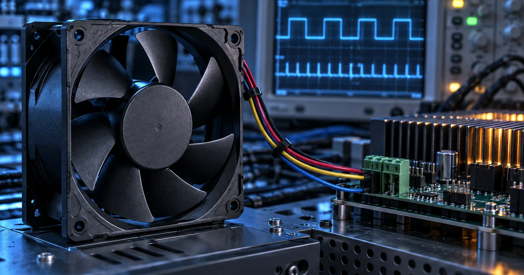
Why the fan passes the bench test and fails in the product
A cooling fan can spin reliably from a laboratory supply and still fail when the product starts several loads through a long harness, a converter and a protection circuit.
The failure is often described as 'the fan does not start', but that phrase hides several different events. The motor may not receive its rated voltage. The driver may reset while the supply is recovering. The controller may command a low PWM duty before the rotor has reached stable speed. Or the impeller may start mechanically and then stall when the real filter, heatsink or grille adds pressure. Each event leaves a different trace on the voltage, current and FG or RD signal.
The bench test normally removes those interactions. A large laboratory supply has short leads and a generous current limit. It may be set to a fixed voltage at the fan connector. The fan may be running free-air, without the enclosure resistance that shifts its operating point. A product test adds the opposite conditions: a converter with a current limit, a harness with resistance, several fans starting together, a cold bearing, a restricted inlet and a controller that releases the PWM command gradually.
The first design decision is therefore not a fan model. It is the definition of the start event. Record the supply at the fan pins, the current at the fan, the PWM command, the time to stable RPM, the airflow or pressure condition and the temperature. If the system has multiple fans, define whether they start together, in groups or one at a time. A start requirement without that sequence cannot be validated or quoted consistently.
The startup current is a system event
The current shown on a catalogue line is normally a running value. Startup is a transient in which the controller, converter, wiring and fan driver interact.
A brushless DC cooling fan contains electronics as well as a motor. At enable, the driver must establish rotor position, charge internal capacitors and accelerate the impeller against aerodynamic and bearing resistance. The current waveform can therefore have an initial peak, a commutation pattern and a settling period before it reaches the normal running value. The height and duration depend on voltage, temperature, control state, mechanical load and the specific fan design.
Do not treat the peak as a single universal number. A current probe at the converter output may show the input current of the converter, while a probe at the fan lead shows the fan-side transient. A slow multimeter can show neither. Use a current probe or a low-inductance shunt with a differential measurement, and state the bandwidth and sample rate. The record should show the first edge, the maximum value, the time above the steady current and the voltage at the same instant.
The converter sees the sum of all fans and every other load that starts with them. If three fans have similar start profiles and the controller enables them together, the transient can be close to three times a single-fan event before the converter's control loop responds. That does not mean the exact multiplication is guaranteed; harness impedance, phase differences and current limiting change the shape. It does mean that testing one fan cannot prove a multi-fan start.
A reliable design has margin in both current and voltage. The converter must supply the transient without entering hiccup or foldback, the protection device must not open, and the fan-pin voltage must remain inside the selected family's operating range. If the converter cannot provide that margin, changing the PWM duty does not fix the supply architecture.
| Measurement | Where to measure | What the trace answers |
|---|---|---|
| Fan-pin voltage | Across the fan supply pins | Does the driver receive enough voltage during acceleration? |
| Fan current | In the fan supply lead | What is the peak and how long does it last? |
| PWM command | At the fan control input | Was the fan enabled at a valid command and frequency? |
| FG/RD response | At the fan and controller ends | Did the rotor start and did the feedback survive the transient? |
| Converter output | At the converter terminals | Did the upstream source enter current limit or hiccup? |
| Temperature | Fan inlet, bearing environment and enclosure | Does cold or hot operation change the start margin? |

PWM start command versus running command
The duty cycle that maintains speed is not necessarily the duty cycle that starts the rotor, especially when the inlet and outlet are already restricted.
A four-wire fan normally receives a continuous supply and a separate PWM speed command. The controller may request a low standby speed after boot, but a rotor at zero speed has to overcome static friction, bearing drag and the initial aerodynamic load. If the first command is below the fan family's stable-start region, the fan may twitch, produce a weak FG signal and never reach the speed at which the same duty would be sufficient.
Test the start map separately from the running map. Begin at the specified full or start command, record the time to stable RPM, then step down through the intended operating range. Repeat with a warm restart and a cold start. If the product needs quiet standby operation, validate the transition from start duty to standby duty rather than testing the standby duty from rest.
The command frequency and edge shape matter as well. A controller output that has the correct average duty can still fail if the amplitude, pull-up, reference or frequency is outside the fan input requirements. Measure the PWM waveform at the fan connector. If the fan uses FG or RD, define what the controller considers 'started': a minimum frequency, a number of consecutive pulses, or a time-based confirmation.
Avoid a software-only retry loop that hides a marginal electrical design. Repeated starts can heat the driver, increase acoustic stress and make a field failure intermittent. A retry may be part of a fault strategy, but the normal start must pass with the production voltage, pressure and temperature conditions.
| Control state | Test method | Acceptance evidence |
|---|---|---|
| Cold start | Enable from zero speed at the lowest specified temperature | Stable RPM, voltage and current remain within the defined window |
| Warm restart | Disable and re-enable after the fan reaches operating temperature | No missed start or delayed FG/RD confirmation |
| Start-to-standby | Start at the defined start command, then reduce duty | The rotor remains stable after the transition |
| Pressure-loaded start | Start with filter, grille, heatsink and duct installed | The fan accelerates without repeated stall |
| Fault recovery | Remove and restore command or supply as specified | The controller reports the result and the fan restarts safely |
Cold start, bearing drag and installation pressure
Temperature changes the electrical and mechanical start margin at the same time, while an installed air path changes the load the fan must accelerate against.
A cold fan can have higher bearing drag because lubricant viscosity changes with temperature. The driver and converter also have their own temperature-dependent behaviour. Do not turn a general cold-start statement into a universal temperature promise; define the actual minimum and maximum environment, the soak time and the start sequence, then test the selected sample.
The pressure condition matters even when the fan's free-air airflow looks impressive. A filter, fin stack, louver, grille or narrow outlet moves the fan along its P-Q curve. A fan that starts in free air may stall against the installed resistance if the initial torque and voltage margin are small. That is why the pressure-loaded start belongs in the test matrix, not as a later thermal test.
Measure inlet temperature and pressure drop during the start. A fan that is drawing through a filter can see a changing resistance as the enclosure flow develops. If the pressure is negative at the inlet because of another fan or blower, a starting rotor can see an operating condition different from the final steady state. The direction of each fan and the sequence of parallel fans must be recorded.
When the cold result fails, separate the choices: improve voltage margin, change the start command, reduce the initial system resistance, change the bearing or fan design, or stage the other loads. Do not claim that a larger free-air CFM number will solve a pressure-loaded start without checking the actual curve and assembly.
Multiple fans: inrush, sequencing and reverse flow
A fan bank is not one larger fan. Its start sequence, shared supply impedance and idle-fan flow path can determine whether every fan reaches stable speed.
When several fans share a converter, the start problem has a scheduling dimension. Simultaneous enable gives the shortest total start time but the highest current transient. Sequential enable spreads the transient but can expose the first fan to a different pressure condition while the other paths are closed or idle. A design review should state the delay, the group size and the condition that allows the next fan to start.
Measure the fan bank in its final topology. The controller's current reading may show only the total, so add branch measurements or test each branch with a known instrument. Look for the first branch that drops the shared rail, and check whether a stalled fan causes the controller to retry all fans. The protection response should be defined before the thermal test, not invented after a field failure.
Parallel fans also create an air-path problem. An idle fan without a damper or check path can allow reverse flow, reducing the flow through the operating fans and changing their pressure load. The result can be a start failure that looks electrical because the current and voltage change when another fan is disabled. Use smoke, particle visualization or a pressure measurement to confirm the flow direction, and test the idle state as well as all-running operation.
N+1 operation needs its own startup case. If one fan is intentionally unavailable, the remaining fan or fans may have a higher operating point and a different start load. A start test that passes with all fans present does not prove the failed-fan configuration.
| Case | Electrical check | Air-path check |
|---|---|---|
| All fans enabled together | Peak shared current and rail minimum | Flow distribution while every rotor accelerates |
| Staged enable | Delay, branch current and controller timeout | Pressure seen by the first fan and later fans |
| One fan unavailable | Retry and fault current behaviour | N+1 flow, pressure and reverse-flow path |
| One fan hot restart | Restart current after thermal soak | Interaction with fans already running |
| A branch disconnected | Open-circuit alarm and no repeated brownout | No bypass path that starves the remaining fans |
A measurement sequence that finds the real cause
The sequence below turns a vague no-start complaint into a decision about supply, command, mechanics or air path.
Start with a reference run at the fan connector using the production harness and controller, but with the fan in the installed assembly. Capture voltage, current, PWM, FG/RD, RPM, inlet temperature and pressure. Repeat at least three starts so that a marginal event is not mistaken for a pass. Save the raw traces, not only the peak values.
Next remove one restriction at a time while keeping the electrical path unchanged: open the grille, bypass the filter for a controlled test, then restore it. If the fan starts only when the air path is opened, the pressure load or inlet geometry is part of the cause. Do not ship the bypass; use it to identify the mechanism and then redesign or select against the installed point.
Then isolate the source margin. Use a short harness or a local source only as a diagnostic control, and compare the fan-pin waveform. If the local source passes and the product source fails, measure cable, connector, protection and converter resistance. If both fail under pressure, the fan selection or start command needs review. If the voltage is correct but the rotor does not accelerate, inspect the command, bearing condition, mounting distortion and fan-side driver.
Finally test the boundaries: minimum and maximum supply, cold and hot soak, maximum installed pressure, all fan sequences, a brownout recovery and the controller's fault response. A production release should define the pass window for stable RPM and feedback, not merely 'the fan spins'.
Engineer FAQ: fan startup current and low voltage
These answers keep startup failures tied to measurable conditions rather than to a generic current number.
Q: Why does the fan start from my bench supply but not from the product? A: The product can have lower voltage at the fan pins, a current-limited converter, a longer return path, a low PWM start command or a higher pressure load. Capture the same signals in both setups.
Q: Can I solve a low-voltage start by increasing the supply setting? A: Only within the fan's specified voltage range. Do not overdrive a 12 V fan to compensate for wiring loss. Reduce the loss, improve source margin or select the correct voltage family.
Q: Is startup current always several times the running current? A: There is no universal ratio. Measure the selected fan and interface. The peak depends on the driver, voltage, temperature, mechanical load, control command and measurement bandwidth.
Q: Should all fans start at once? A: Not automatically. Compare simultaneous and staged start against converter capacity, thermal time, fault response and air-path interaction. The selected sequence must be validated as part of the product.
Q: What does FG or RD prove during startup? A: It can show that the rotor has reached a defined speed or that a fault output is active, but the controller must define the pulse threshold, timeout and missing-signal response. A single transition is not the same as stable operation.
Q: What should a custom sample prove? A: Fan-pin voltage, startup current, time to stable RPM, PWM response, FG/RD behaviour, airflow, static pressure, temperature rise and the effect of the production harness and mounting.
Questions for a Design Review
Use these questions before approving a fan, converter or startup sequence.
- What voltage does the fan actually receive at the connector during the first transient, and what is the minimum permitted value?
- What are the startup peak current, time above running current and total current when every fan and companion load starts together?
- Does the controller start at a defined command that the selected fan can use from zero speed, then transition to the standby command?
- What are the cold-soak temperature, hot-soak temperature, start delay and stable-RPM or FG/RD acceptance criteria?
- Has the start been tested with the real filter, grille, heatsink, duct, cable route and mounting condition?
- What happens when one fan is missing, disconnected or slower, and does the remaining air path create reverse flow?
- Can the converter recover from a brownout or fan fault without repeatedly cycling the fans and stressing the driver?
From a startup failure to a validated fan sample
MEGA Tech develops and manufactures custom cooling fans—from fan selection, air-path review and sample validation to volume production. We can work from the required frame and thickness, voltage tolerance, airflow, static pressure, speed, PWM command, FG or RD output, connector, bearing and environment. The selection is made from the installed duty point rather than from a part number or a same-size comparison.
For a startup investigation, send the fan size, supply architecture, voltage tolerance at the fan connector, airflow and static-pressure target at that airflow, start command and PWM frequency, FG/RD requirement, connector and harness, mounting and inlet clearance, start-time limit, noise target, temperature, altitude, dust or moisture exposure and life assumption. A measured voltage waveform and the system P-Q resistance are especially useful when the fan passes on the bench but fails after installation.
Our scope is the custom cooling fan and its engineering validation. The complete cabinet, heat exchanger, coil, liquid loop, system controller and safety design remain with the system integrator. A successful result is a representative sample tested with the production-relevant power, command, air path and mounting conditions.
- Custom DC and EC fans in axial and centrifugal formats
- Selection by airflow, static pressure, voltage and control interface
- Startup current, voltage sag and FG/RD response reviewed with the sample
- Sample validation in the customer's representative assembly
