

The motor technology was chosen before the air path was understood
AC and EC fans can both move air, but the right comparison starts with the installed duty, not with a free-air catalogue number.
An HVACR or industrial-cabinet team may begin with a familiar question: should the next fan be AC or EC? The question is useful only after the heat load, allowable temperature, filter condition, coil resistance, acoustic limit and duty cycle are visible. A fan that looks efficient in free air can miss the installed operating point once a grille, filter, condenser coil or compact duct is added.
AC axial fans are often attractive when the equipment already has a 110 V or 220 V branch, the airflow demand is stable and the control system only needs switching. EC fans can be attractive when the equipment needs variable speed, demand response, lower part-load energy or a broad adjustment range. Neither technology automatically wins on airflow, pressure, noise or service life.
This guide gives engineers a practical comparison for electrical cabinets, condensers, heat exchangers, power supplies and outdoor equipment. MEGA Tech develops and manufactures custom cooling fans and supports fan selection, air-path review, sample validation and volume production; the complete cabinet, coil, controller and system integration remain with the equipment manufacturer or system integrator.
Start with heat load and required operating points
Technology selection is only meaningful when the thermal requirement is converted into airflow and pressure at the actual condition.
List the heat sources first: drives, power supplies, transformers, rectifiers, contactors, compressors, inverters and other components. Record the heat rejected into the air path and the highest allowable component or internal-air temperature. For an enclosure, include the ambient range, solar exposure where relevant and the temperature rise that the equipment can tolerate.
Then define the required airflow at the thermal operating point rather than copying maximum CFM. A filter, louvre, guard, coil, grille, duct transition or cable obstruction adds pressure. Build a system resistance estimate and state the pressure units consistently. If the duty changes with outdoor temperature or load, define more than one operating point instead of approving a single nominal condition.
An AC fan may be sufficient when the required point is stable and the equipment naturally cycles between on and off. An EC fan may justify its cost when the heat load spends significant time below peak, when airflow must follow a temperature signal, or when the equipment has a strict energy budget. The decision should be traceable to those conditions.
| Design question | AC fit | EC fit |
|---|---|---|
| Stable fixed airflow | Simple line-voltage switching | Possible, but control may be unnecessary |
| Variable heat load | Use staged fans or approved control if documented | Variable speed can track demand |
| Existing 110/220 V branch | Direct architecture may be straightforward | Check integrated electronics and control wiring |
| High filter or coil resistance | Select the exact pressure curve | Select the exact curve at the commanded speed |
Compare the electrical architecture, not only the label
The supply, control interface, protection and wiring can change the real project cost more than the fan price.
A fixed-speed AC fan can connect naturally to a line-voltage branch through a relay, contactor, thermostat or approved switching device. The design still has to check rated voltage, frequency, terminal voltage under load, current, input power, inrush or startup behavior and protective coordination. A nominal 220 V supply is not proof that the fan sees 220 V at its terminals during a demanding start.
An EC fan usually adds an electronic commutation and control layer. That can enable proportional speed, but it also introduces requirements for the control signal, power quality, fault behavior, electromagnetic compatibility review and service documentation. The exact interface varies by product, so do not assume that every EC fan accepts the same command, feedback or restart sequence.
For either technology, document the fan code, voltage, frequency, control method, guard, connector or lead arrangement and mounting direction. If the design has several fans, check simultaneous startup, sequencing, branch protection and the effect of one fan being unavailable. The fan selection must match the released wiring diagram, not only the sample on the bench.
Part-load efficiency matters only when the system can use it
EC speed control can reduce energy at part load, but the installed system, control law and minimum acceptable airflow determine the benefit.
A variable-speed fan can reduce airflow when the equipment heat load is low, which may reduce fan power and noise. The saving depends on the fan curve, motor efficiency, control setting, system resistance and time spent at each load. It should be calculated from measured or documented operating points, not from a general statement that EC is more efficient.
A fixed-speed AC fan can still be the better engineering choice when the cabinet has a narrow duty range, the fan runs infrequently, the controls are intentionally simple or the available EC interface would add more integration risk than value. Staged AC fans can provide coarse capacity steps, but the transition noise, cycling frequency and thermal hysteresis must be validated.
For HVACR equipment, compare the fan energy with the whole heat-rejection path. A lower fan input can be offset if the selected operating point does not move enough air through the condenser or coil. For cabinets, compare the fan energy with the component derating requirement and service conditions. The goal is a stable thermal result with a documented energy behavior.
Build the duty profile from the equipment, not from the fan brochure. Note the hours at standby, normal load, peak load, high ambient and maintenance condition. Then calculate or measure the airflow command and pressure point for each state. An EC solution earns its complexity when the operating profile contains meaningful time away from peak and the control can follow it without hunting. If almost all hours sit at one stable point, a correctly sized AC fan may deliver the simpler and more robust result.
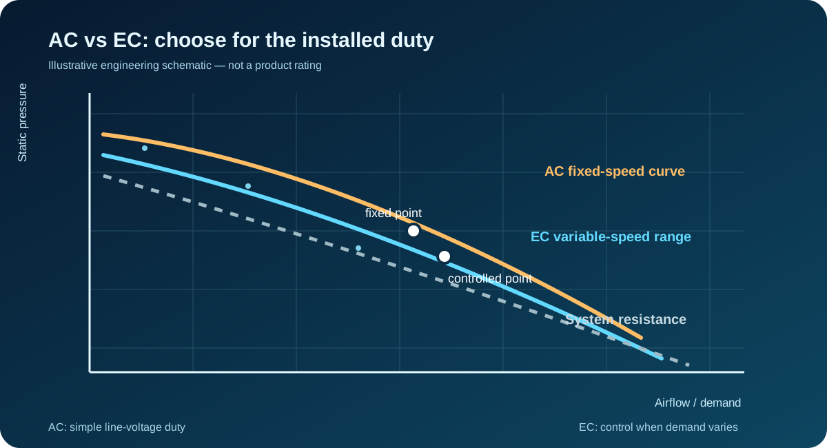
Pressure, filters and coils can reverse the apparent choice
A fan with a higher free-air value is not necessarily the better choice once the system resistance is included.
The installed path can include an inlet screen, washable or replaceable filter, heat exchanger, condenser coil, louvre, grille, duct bend and discharge restriction. Each element changes the pressure the fan must overcome. Dirty filters and coil fouling move the system curve again, so the approved design should include the maintenance condition that matters for the equipment.
When comparing AC and EC, overlay the exact fan curves on the same system curve. For EC, repeat the overlay at the commanded speed range and identify the minimum speed that still meets the thermal target. For AC, use the correct voltage and frequency curve. Do not compare a maximum AC point with an EC point that was measured at a different restriction.
A practical sample test records airflow or pressure, inlet temperature, outlet temperature, fan current, input power, speed where available and component temperature. Keep the guard, filter, coil, cutout and mounting orientation fixed. If one technology uses a different frame or guard, treat that packaging difference as part of the comparison rather than attributing every result to the motor.
Noise and vibration need an installed comparison
Motor technology can affect acoustic behavior, but air velocity, mounting and structure often dominate the result.
Measure sound with the real guard, grille, filter and enclosure panels. Record distance, background level, operating point and whether the sound is broadband, tonal or structure-borne. A variable-speed EC control can reduce noise at light load, but a poorly tuned command can create hunting or a tonal change. A fixed-speed AC fan can be quiet when its operating point and mounting are well matched.
Vibration comes from more than the motor. Imbalance, bearing condition, mounting stiffness, panel resonance, fan-to-frame clearance and airflow separation can all influence the result. A change from AC to EC does not remove the need to check fasteners, gaskets, isolation, cable routing and structural response.
For a production decision, define the acoustic and vibration acceptance limits before testing. Repeat at startup, steady state, minimum and maximum commanded speed where applicable, warm condition and the most restrictive filter state. If the result changes after installation, inspect the air path and structure before changing the fan technology.
Control strategy is part of the thermal design
An EC fan cannot compensate for an unclear control law, and an AC fan cannot be judged fairly when the switching strategy is unfinished.
Define what controls the fan: component temperature, enclosure air temperature, coil temperature, pressure, system load or a schedule. State the sensor location, sampling interval, hysteresis, ramp rate, minimum speed and failure response. These choices determine whether the fan provides stable cooling or repeatedly hunts around a threshold.
For switched AC fans, check relay life, contact bounce, restart timing, thermal cycling and the behavior of multiple fans. If fans are staged, define the step points and confirm that the airflow changes do not create an unacceptable acoustic event. If a thermostat or controller is supplied by the system integrator, test the exact production device.
For EC fans, check the command range, signal reference, feedback interpretation, loss-of-command behavior, restart behavior and any product-specific limits. Do not promise PWM, 0-10 V, tachometer, alarm or remote control unless the selected variant documents it and the sample confirms it. The application team owns the final control and safety qualification.
Outdoor HVACR adds ambient, contamination and service constraints
The best motor choice on a clean indoor bench may fail the outdoor maintenance and weather duty.
Outdoor equipment sees changing ambient temperature, rain exposure, dust, pollen, salt or industrial contaminants. The fan, guard, filter and coil must be considered as one air-path assembly. A tighter filter may protect the heat exchanger but also increases pressure and reduces airflow as it loads.
For condensers and heat exchangers, confirm whether the fan is pushing or pulling through the coil, where recirculation can occur and how the service team will clean the path. Check clearance on the inlet and discharge sides. A fan selected without the shroud, louvre or coil geometry may not deliver the useful face airflow the thermal design assumes.
The production sample should be tested at representative ambient and restriction conditions, with the maintenance state defined. Record the fan configuration and do not infer a complete system protection rating from the fan selection alone. The system manufacturer remains responsible for the overall enclosure, coil, refrigerant circuit, controls and environmental qualification.
Industrial cabinets reward simple decisions when the duty is simple
For a fixed heat load and a known service environment, an AC fan can reduce integration complexity; for changing loads, EC control may add useful margin.
A drive or power-supply cabinet often has a predictable airflow direction and a clear branch supply. In that case, an AC axial fan may provide a direct, serviceable solution. The selection still needs the exact pressure curve, filter loss, inlet temperature and component temperature. A large maximum-airflow number cannot replace the operating-point check.
If the cabinet spends most of its time at low load but occasionally reaches a high power step, EC control may reduce energy or noise during normal operation while preserving peak airflow. That benefit must be weighed against the controller, wiring, fault handling and validation work. A staged bank of AC fans may also meet the requirement when the thermal steps are broad and predictable.
For either choice, leave service access for filter replacement and fan inspection. Keep the cable route away from the rotor and maintain the required clearance around the inlet and outlet. The released drawing should identify fan type, frame size, voltage, frequency, control, airflow direction and the conditions used for approval.
A controlled AC-versus-EC sample plan
A fair comparison changes one variable at a time and tests the production air path, not an idealized laboratory setup.
Freeze the test matrix before samples arrive. Record the fan series and type, frame, voltage, frequency, control state, guard, gasket, connector, mounting orientation, filter, grille, coil or duct and heat load. Identify which values are catalogue references and which values are measured in the installed assembly.
Run at least the nominal operating point and the most important low-load and high-load conditions. Measure terminal voltage, frequency, current, input power, airflow or pressure, inlet and outlet temperature, component temperature, sound and vibration. For EC, record command and feedback. For AC, record switching and restart behavior.
Repeat the critical points after the system reaches steady temperature and after the relevant restriction is introduced. Check startup after a warm soak, repeated cycling and the maintenance state defined by the equipment specification. Approve the selected technology only against written limits. If both pass, choose based on integration, energy, noise, service and supply priorities rather than a generic technology preference.
Keep the comparison package readable for the next design review. Show the fan identity, test date, instrument method, air-path drawing, control setting and acceptance result beside each operating point. If a controller, filter or coil changes after the sample test, mark the result as no longer equivalent and repeat the affected point. This is especially important when an AC sample is replaced by an EC alternative: similar frame dimensions do not prove similar pressure, wiring, control or acoustic behavior. Clear evidence makes approval and later service decisions faster for every reviewer.
Engineer FAQ
Short answers before selecting AC or EC for a production cooling path.
Q: Is EC always more efficient? A: Not automatically. Part-load benefit depends on the duty profile, control law, pressure path and measured operating point.
Q: Is AC only for old equipment? A: No. AC can be a sound choice for stable fixed-speed line-voltage duties when the installed airflow, pressure, noise and electrical conditions are correct.
Q: Can I compare maximum CFM between AC and EC? A: No. Compare the exact curves at the same voltage, frequency, speed or command, restriction and measurement method.
Q: Should I change from AC to EC to solve a hot cabinet? A: First measure heat load, filter pressure, bypass, recirculation, terminal voltage and the actual fan operating point. The root cause may be the air path.
Q: What should accompany a custom fan request? A: Send size, voltage, frequency, target airflow, static pressure, quantity, noise limit, control method, mounting and application environment.
Q: Does MEGA Tech supply the complete HVACR or electrical cabinet? A: No. MEGA Tech is the custom cooling-fan manufacturer. The complete cabinet, coil, controller, compressor and system integration remain with the equipment manufacturer or system integrator.
Questions for your next AC or EC review
Use this checklist before freezing the fan technology and releasing samples.
- What heat load, ambient range and component temperature limit define the required airflow?
- What pressure comes from the filter, grille, guard, coil, duct, louvre and service condition?
- Is the duty fixed-speed, staged or continuously variable, and why?
- What voltage and frequency are present at the fan terminals during startup and steady operation?
- If EC is considered, what command, feedback, fault and restart behavior does the exact variant document?
- If AC is considered, what switching, startup, cycling and branch-protection behavior must be validated?
- Have AC and EC been compared at the same installed air path and thermal load?
- Are noise, vibration, filter loading and service access included in the approval criteria?
- What production drawing records the fan code, frame, voltage, frequency, control, airflow direction and test condition?
- What information should accompany a sample request: size, voltage, frequency, airflow, pressure, quantity, noise and environment?
