
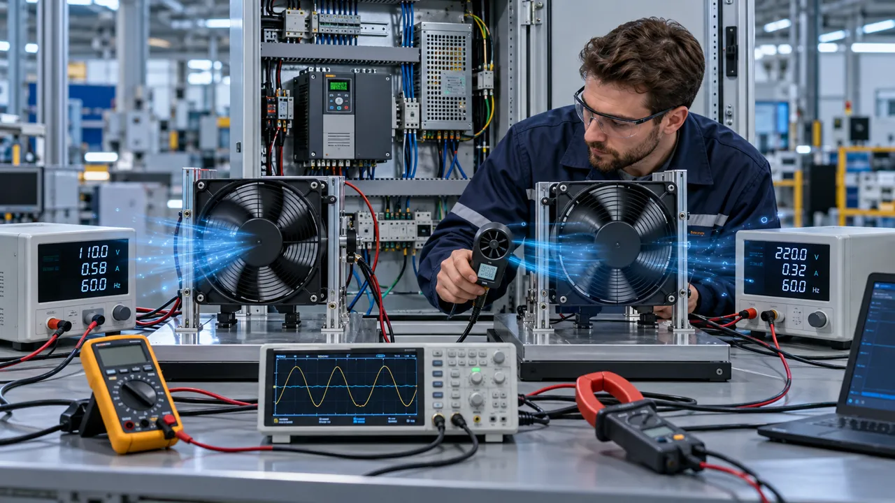
The voltage label was correct and the cooling result was still wrong
110 V and 220 V identify the electrical interface. They do not, by themselves, identify the airflow, pressure, noise or installed thermal result.
A machine builder approved a 220 V AC axial fan because the nameplate matched the factory supply. During commissioning, the cabinet cooled less effectively than the prototype. The replacement fan was electrically compatible, but the test had used a different frequency curve, a different guard and a cleaner air path. The voltage label had been treated as the whole selection decision.
The same mistake appears in export equipment. A design team develops around a 220 V, 50 Hz supply, then ships a similar-looking 110 V or 60 Hz version into another market without rechecking current, speed, pressure, noise and the system curve. The fan may run, yet the thermal margin, acoustic signature and protection behavior can change.
This guide gives engineers a practical way to compare 110 V and 220 V AC cooling fans for electrical enclosures, VFD cabinets, UPS equipment, power supplies, refrigeration equipment and heat exchangers. It uses the current AC catalogue as the product reference. MEGA Tech develops and manufactures custom cooling fans, supports fan selection, air-path review, sample validation and volume production; the equipment power system and complete machine qualification remain with the system builder.
Separate four questions that are often collapsed into one
A sound voltage decision answers four different questions: supply compatibility, fan performance, control behavior and safety documentation.
First, can the fan receive the voltage that the equipment provides at its terminals under load? The answer includes tolerance, wiring drop, switching device, protective device and service isolation. A nominal 220 V supply that falls during a large motor start is not the same electrical condition as a stable laboratory source.
Second, what airflow and pressure does the fan produce at that voltage and frequency? The answer comes from the exact product record and P-Q data, not from the voltage printed in a product family name. Current, input power, speed, maximum airflow, maximum pressure and noise should be read together.
Third, how is the fan controlled? A fixed-speed line-voltage fan may be switched by a thermostat, contactor or relay. If the equipment needs proportional speed, low-voltage backup, PWM, feedback or a special start/stop sequence, that is a separate requirement that must be included in the fan specification and sample test.
Fourth, what evidence does the equipment manufacturer need for its market and safety process? The fan's product documentation supports the system file, but it does not automatically certify the complete machine. Keep the fan configuration, test evidence and change-control record aligned with the actual production part.
| Question | Evidence | Common mistake |
|---|---|---|
| Can it connect? | Terminal voltage, tolerance, frequency and wiring | Selecting from the facility voltage only |
| Will it cool? | P-Q curve at the actual condition | Comparing maximum CFM |
| Can it be controlled? | Switching, start, feedback and control interface | Assuming voltage equals speed control |
| Can we release it? | Configuration and system documentation | Treating a component mark as machine approval |
110 V versus 220 V: what changes and what does not
For a comparable power level, the higher-voltage variant can carry lower current, but fan performance is governed by the exact motor and rated operating condition.
At the equipment level, a 220 V fan can reduce current in the branch circuit compared with a similar power load at 110 V. That can influence wire sizing, connector selection, switching contacts and distribution losses. It does not mean that every 220 V fan consumes less input power or produces more airflow than every 110 V fan. Compare the catalogue entries for the same series, frequency and operating condition.
The current AC catalogue includes 110 V AC and 220 V AC variants across the active AC axial fan families. For example, the MG12025 record lists both voltage variants and provides separate current and power values in its table. The correct selection still depends on the target operating point, because a 120 mm fan behind a coil or filter may operate far from its maximum-airflow point.
Do not redesign a winding or substitute a voltage by changing external wiring. The fan's rated voltage is part of its motor configuration. Applying 220 V to a 110 V model, or treating a 110 V model as a universal 220 V replacement, can create an immediate safety and reliability problem. Use the exact model and voltage code that the manufacturer documents.
50 Hz and 60 Hz must stay visible in the specification
Frequency changes can move the fan operating point and the electrical, acoustic and thermal behavior at the same time.
Many AC catalogue pages show 50 Hz and 60 Hz data because the operating frequency is not a cosmetic regional label. Speed can change, and airflow and pressure can move with it. Input power, current, motor heating and tonal noise can change as well. A design that uses the 60 Hz maximum airflow as its 50 Hz selection value is not a controlled design.
When one product will ship to both 50 Hz and 60 Hz markets, decide whether one configuration is approved for both conditions. If yes, test both at the actual voltage, air path and heat load. If the product code or approved operating range changes, make that distinction visible in the BOM, nameplate and service documentation. Do not leave the production team to infer it from the destination country.
A frequency review also protects the P-Q comparison. Overlay the fan curve for the actual frequency with the system curve for the real enclosure, coil, grille or filter. Record the expected operating point and then measure the production sample. If the result differs, investigate voltage at the terminals, frequency, wiring, restriction and fan identity before changing the design.

Current, power and protection belong in the same review
A fan can meet the airflow target and still be a poor electrical fit if the startup, switching and protection conditions are ignored.
Record rated current and input power for the exact voltage and frequency. Then check the equipment branch protection, relay or contactor rating, connector temperature and wire routing. If several fans start together, the aggregate behavior can differ from the single-fan catalogue value. A staged start or a control interlock may be needed, but that decision belongs to the system designer and must be tested with the production controller.
Measure the voltage at the fan terminals during startup and steady operation. Long cable runs, undersized conductors, loose terminals and shared loads can create a drop that changes the motor condition. A fan that looks underperforming may be receiving the wrong voltage at the point of use. Conversely, a high line condition can increase stress and noise.
Protection must also cover abnormal conditions: blocked airflow, stalled or obstructed rotor, repeated cycling, high ambient and a dirty filter. The exact protective behavior depends on the product configuration. Do not promise a thermal protector, alarm output or restart behavior unless it is documented for the selected variant and confirmed in the sample.
Voltage does not replace the installed P-Q selection
After electrical compatibility is confirmed, the fan still has to produce useful airflow through the real pressure path.
The system curve is built from the enclosure or heat-exchanger path: filter, grille, louvre, coil, duct, cable obstruction, guard and discharge opening. The fan curve is selected at the actual voltage and frequency. Their intersection is the expected operating point. This remains true whether the fan is 110 V or 220 V.
The current AC catalogue covers compact and large axial formats. An MG12025 example lists maximum airflow values of 64/76 CFM and maximum air-pressure values of 5/5.5 mmH2O in its record, while the much larger MG22060 record lists 480/520 CFM and 30.48 mmH2O. These values show the scale of the range, not a universal performance guarantee for a loaded cabinet or coil.
When comparing voltage variants, hold the air path constant. Use the same cutout, guard, filter, mounting orientation and measurement method. Otherwise, the test can falsely attribute a change caused by packaging to the electrical voltage. A clean comparison changes one variable at a time and records temperature, airflow, pressure, current, power and noise.
Export equipment needs a voltage strategy, not a last-minute substitute
Global equipment should define its regional electrical variants before the fan, wiring and enclosure are frozen.
List the target markets and their supply assumptions at the beginning of the project. Then decide whether the product uses a 110 V fan, a 220 V fan, multiple approved variants, or a different DC/EC architecture. Keep the fan code, wiring diagram, protective device, label and service instruction consistent with that decision.
A dual-market design should be reviewed for more than the motor. The electrical cabinet may use different contactors, fuses, connectors, wire lengths and clearances. The equipment's internal heat load may also differ if the power electronics or transformer changes. A fan variant that is acceptable in one configuration is not automatically approved in another.
Sample-test every released configuration that materially changes voltage, frequency, wiring, guard, control or air path. Keep a traceable record of the fan series, voltage, frequency, test environment and acceptance result. This prevents a distributor or assembly line from treating two visually similar fans as interchangeable.
For commissioning, prepare a simple comparison sheet before the first production build. Put the 110 V and 220 V records in separate columns, then add the measured terminal voltage, frequency, current, input power, airflow or pressure, inlet temperature and component temperature. Add the guard, filter, grille and mounting orientation as controlled fields rather than free-text notes. This makes a regional change reviewable by design, manufacturing and service teams. It also exposes a common false comparison: one sample is tested on an open bench while the other is tested behind the production restriction. The voltage decision should be made from like-for-like installed evidence, with any remaining difference assigned to the correct cause.
The same sheet should preserve the acceptance limits and the measurement method. State whether airflow is reported as free-air flow, duct flow or a value inferred from pressure, and state where sound is measured. Note whether the fan is new, run-in, filtered or exposed to a warm enclosure. These details are not paperwork for its own sake: they prevent a later supplier comparison from mixing catalogue maximums with installed results. When the equipment is revised, repeat the fields that can affect the result instead of copying the old conclusion forward. A clear record makes the sample decision easier to explain and safer to reproduce.
When DC or EC is a better comparison
AC is often practical for fixed-speed line-voltage airflow, but the equipment requirements may point to DC or EC.
AC axial fans can fit equipment that already has a 110 V or 220 V branch and needs straightforward fixed-speed ventilation. They can be a good fit for industrial cabinets, power supplies, condensers and heat exchangers when the operating point and service condition are stable. The correct AC choice is still the one whose pressure, noise and electrical behavior fit the assembly.
Compare DC when the equipment already has a low-voltage bus, battery backup, PWM requirement or feedback interface. Compare EC when variable-speed efficiency, demand control and wide turndown are central to the product. Do not compare technologies by free-air CFM alone. Use the same installed airflow, pressure, ambient, control state and acoustic target.
A technology change can affect EMC, wiring, standby behavior, control software, fault reporting and service procedure. Make the comparison with the full system team. MEGA Tech can review fan selection, air path, sample validation and production requirements, while the equipment manufacturer owns the final power architecture and system qualification.
A practical 110/220 V sample-validation plan
The sample test should prove the fan at the voltage and frequency that the production equipment will actually use.
Freeze the configuration first: exact fan series and type, voltage, frequency, bearing, guard, gasket, connector or leads, mounting orientation and control method. Record the actual terminal voltage rather than only the upstream supply. Keep the fan drawing and product data linked to the sample identifier.
Run a steady-state test at the defined heat load. Measure inlet temperature, protected component temperature, airflow or pressure, fan current, input power, speed where available and acoustic response. Repeat at both 50 Hz and 60 Hz when the product is intended for both markets. Use the production filter, grille, coil and guard.
Test switching and restart behavior with the real relay, contactor or controller. If several fans start together, measure the group behavior. Check the high-ambient condition and the service condition that the equipment specification defines. If the fan is stopped or obstructed during a fault test, follow the equipment safety procedure and record the fan-side result without claiming a system safety certification.
Approve only against written criteria. If the 110 V and 220 V variants both meet the thermal target, keep their electrical and acoustic records separate. If one variant misses, do not hide the difference by changing the label; change the fan, air path, control or system design and repeat the review.
Engineer FAQ
Short answers before releasing a 110 V or 220 V AC fan into production.
Q: Is 220 V always better than 110 V? A: No. It may reduce branch current for a comparable power load, but fan performance depends on the exact motor, frequency, air path and product record.
Q: Can I run a 110 V fan on 220 V with a different wire connection? A: No. Use the rated voltage configuration documented for the exact fan model. Do not create an unverified motor condition.
Q: Does the same fan have the same performance at 50 Hz and 60 Hz? A: Not necessarily. Use the frequency-specific curve and validate speed, airflow, pressure, current, power and noise.
Q: What should I check if a correct-voltage fan is noisy? A: Check frequency, terminal voltage, guard, mounting resonance, airflow restriction, bypass and the exact fan variant before reducing speed.
Q: What information should accompany a custom AC fan request? A: Send size, voltage, frequency, target airflow, static pressure, quantity, noise limit, control method, mounting, ambient and application environment.
Q: Does MEGA Tech supply the complete electrical cabinet or refrigeration system? A: No. MEGA Tech is the custom cooling-fan manufacturer. The complete cabinet, controller, coil, compressor and system integration remain with the equipment manufacturer or system integrator.
Questions for your next voltage-selection review
Use this checklist before freezing the fan code for a regional equipment variant.
- What voltage is present at the fan terminals during startup and steady operation?
- Which 50 Hz or 60 Hz curve applies to the released configuration?
- What airflow and static pressure are required at the installed system operating point?
- Are current, power, switching, wire, connector and protective-device ratings documented?
- Does the selected variant have the required control, feedback, restart and fault behavior?
- Does the 110 V or 220 V configuration use the same guard, mounting, filter and air path as the sample?
- What changes between export markets: supply, frequency, wiring, power electronics, ambient or service condition?
- Have both regional variants been tested at the production heat load and acoustic limit?
- What is the approved substitute policy if purchasing cannot obtain the original fan?
- What exact information should accompany a sample request: size, voltage, frequency, airflow, pressure, quantity, noise and environment?
